The DS2401 is a chip that Maxim sells as a “Silicon Serial Number”. That’s pretty much what it is: a chip that contains a serial number which you can read out using a digital interface. This is useful if you’re producing a large number of identical devices but you want to give each one a unique number so you can track each individual device. This chip contains 64 bits of information, consisting of one eight-bit number indicating the chip family (for the DS2401 it’s 01), a 48-bit serial number, and an eight-bit checksum to verify the number is correct. Maxim guarantees that no two DS2401s will have the same serial number, so in theory they can produce 248 = 281,474,976,710,656 of these chips before they run out of numbers.
The DS2401 has a One-Wire interface, which is a clever serial interface designed by Dallas Semiconductor. It has one ground and one active wire, which doubles as data and power supply. The chip gets its power from this wire, and contains an on-board capacitor to store charge so it can keep working even if the data line is “low” for a certain amount of time.
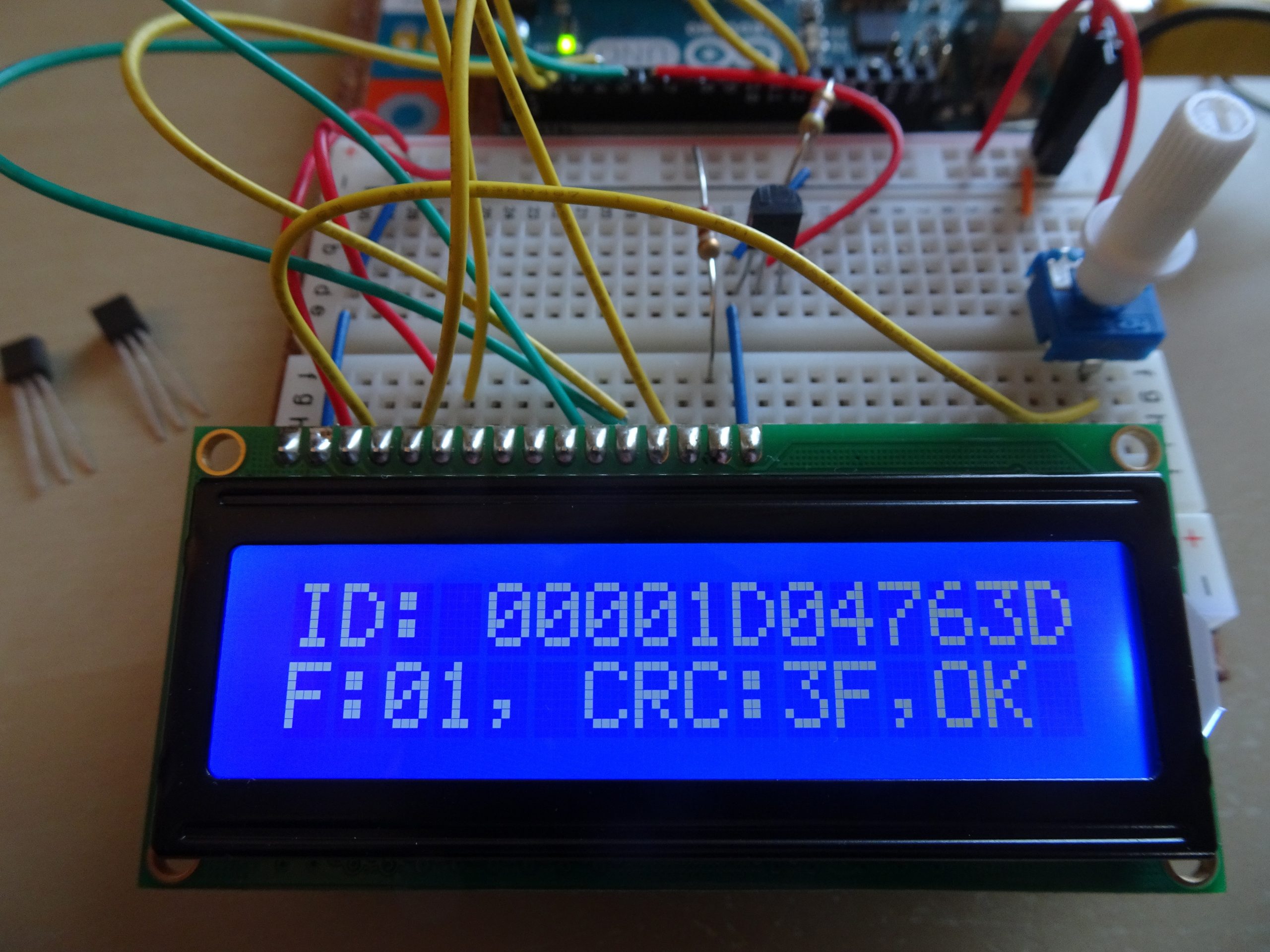
The One-Wire interface is quite easy to use, and it takes just a few lines of Arduino code to read out the serial number from the DS2401. I bought three of these chips, which turned out to have serial numbers 00001D04714B, 00001D04763D and 00001D0498E7. As you can see they’re not exactly consecutive, but since they came as loose chips in a bag there’s no way of keeping them in the right order anyway.
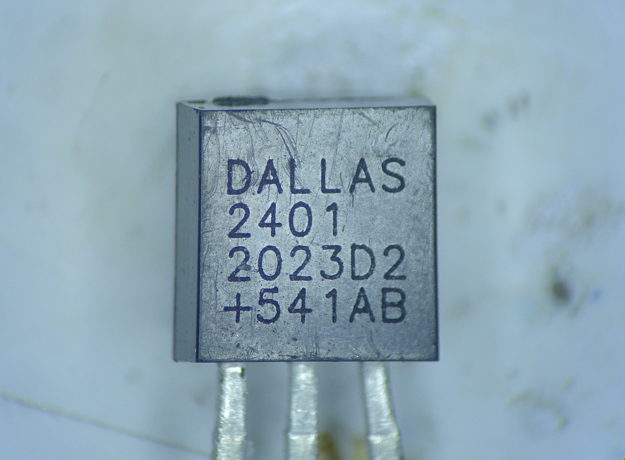
Here’s a mugshot of today’s victim, number 00001D04763D. The codes on the package are not related to the serial number; all three of my chips have exactly the same codes. It’s interesting to see that the 2401 is still labelled “DALLAS”, even though Dallas Semiconductor was acquired by Maxim in 2001 and they stopped using the Dallas trademark on new products around 2007. The code “2023D2” is likely a date code (2020, week 23?), the “+” means it’s a lead-free device, and “541AB” probably refers to a specific factory or assembly line.
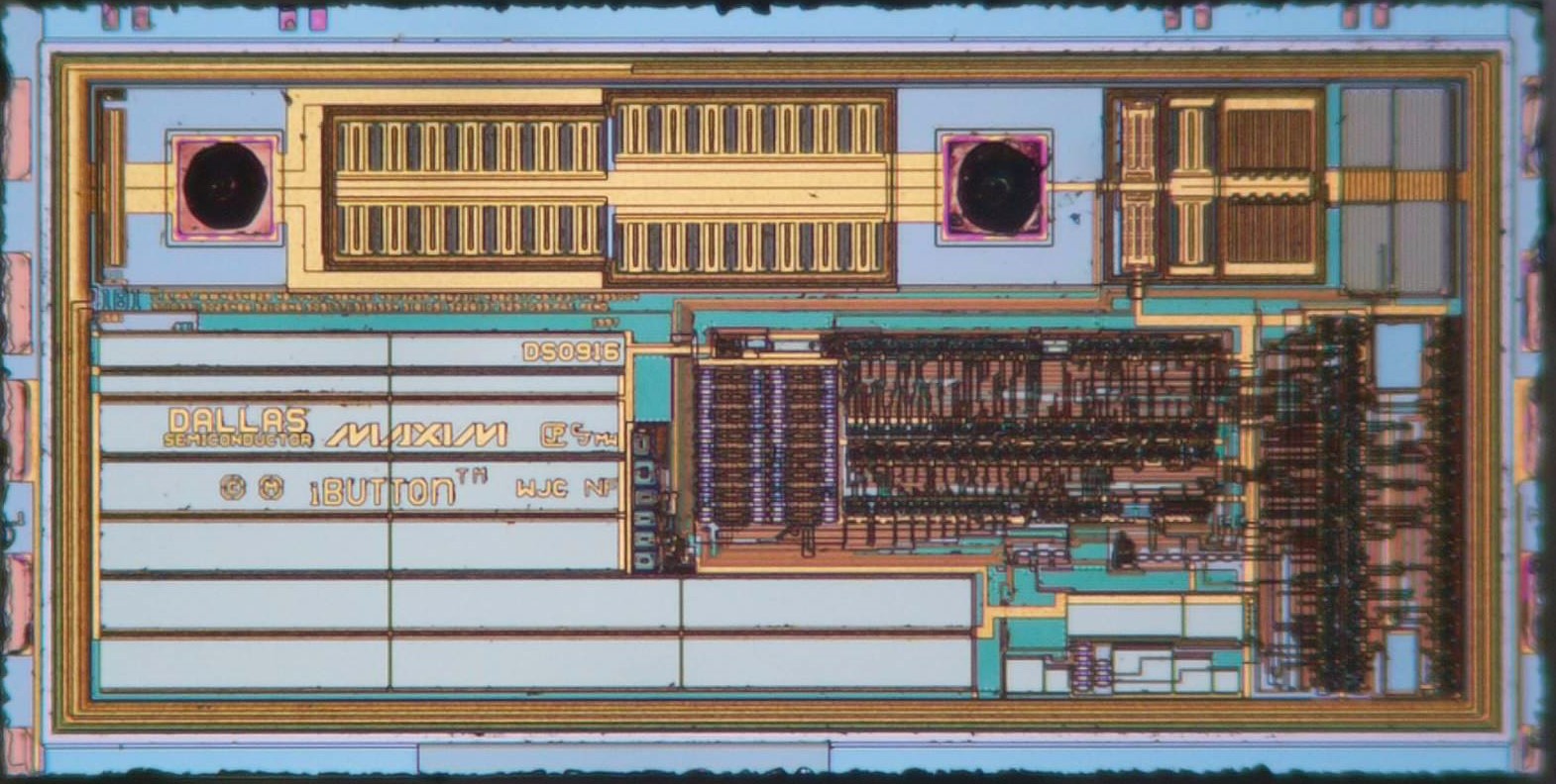
After opening the package, we find a very small chip, measuring just 0.7 by 1.4 mm. At the top we see two bond pads (ground on the left, data/power on the right) with their output driver in between. To the right of the data/power pin we find the input receiver. The lower right part contains digital circuits that implement the state machine and serial interface. The lower left area (light blue with logos on top) is a large capacitor that stores charge to power the device when the data/power pin is low. Finally, right in the middle of the chip is a block of laser fuses that stores the serial number.
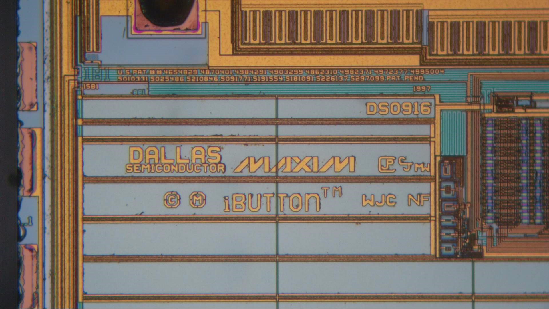
The die contains the logos of Dallas Semiconductor, Maxim (although still the old, angular logo), and iButton, which is the brand under which Maxim sells chips in a coin-shaped package, to be used as access keys, identification keyfobs and so on. We also see a part number “DS0916”, which sounds like a Dallas part number but is not mentioned anywhere in the datasheet. At the top there’s a long list of patents that apply to this design (and several that don’t, really). Finally, there’s a few initials: CJP, CJ, MW, WJC and NF. I haven’t been able to find out whose initials these are; they don’t match any of the inventors mentioned in the list of patents. In fact, most of these list a certain Robert D. Lee, who, among other things, apparently invented the One-Wire interface.
The light blue rectangles seen in this picture are MOS capacitors, which consist of a conductive layer (polysilicon) on top of another conductive layer (diffusion). Together these hold a certain amount of charge that’s used to power the chip.
Here is a close look at the heart of this device: an array of laser fuses that stores the serial number. After the wafer is fabricated, a laser is used to burn away material on each separate chip to create a string of 0s and 1s. The actual fuses are visible here as small rectangular areas, which appear white when encoding a ‘0’ and orange when encoding a ‘1’. The exact contents of this particular device are as follows:
| Hex | 3F | 00 00 1D 04 76 3D | 01 |
| Binary | 0011 1111 | 0000 0000 0000 0000 0001 1101 0000 0100 0111 0110 0011 1101 | 0000 0001 |
| Function | CRC | Serial Number | Device family |
And we can in fact see this string of bits if we follow the numbers and arrows: starting at the green ‘1’, we see ‘0011111’, which corresponds to 0x3F, the CRC code I found on my Arduino. Then follows the serial number (which starts with a long string of 0s), continuing along columns 2, 3 and 4, and finally ending in the indentifier for the chip family, ‘00000001’, on the top left.
In the lower right corner of the chip we see quite a lot of long serpentine resistors (the blue zig-zag shapes). Together with the group of capacitors (light blue rectangles) these likely form timing circuits, to help get the correct timing of bus signals without any external clock reference.
Interestingly, there are a few more laser fuses to be seen: one group of three, a group of six and another group of eight. All appear to be unprogrammed; I’m not sure what their function could be. One likely scenario is that they are used to fine-tune the timing circuits: it is hard to make accurate resistor and capacitor values on a chip (they can vary by up to 50% from one wafer to another), so it may be necessary to provide some means to adjust their values after production.