I recently read a discussion on an electronics forum where someone had trouble getting an IR2104 to work correctly. He had bought these from a shady online store and could not get the correct signals to come out. I offered to analyze the chips, and one of the contributors to that discussion very kindly sent me a couple of them.
The IR2104 is a half-bridge MOSFET driver, which is used to drive the FETs in circuits like DC-DC converters and class-D power amplifiers. It’s made in a high-voltage CMOS process and is capable of driving the high-side FET at voltages up to 600V. The original designer and manufacturer is International Rectifier (IR), one of the first manufacturers of diodes, transistors and power management ICs. Currently the IR2104 is manufactured by Infineon, after it acquired IR in 2015.
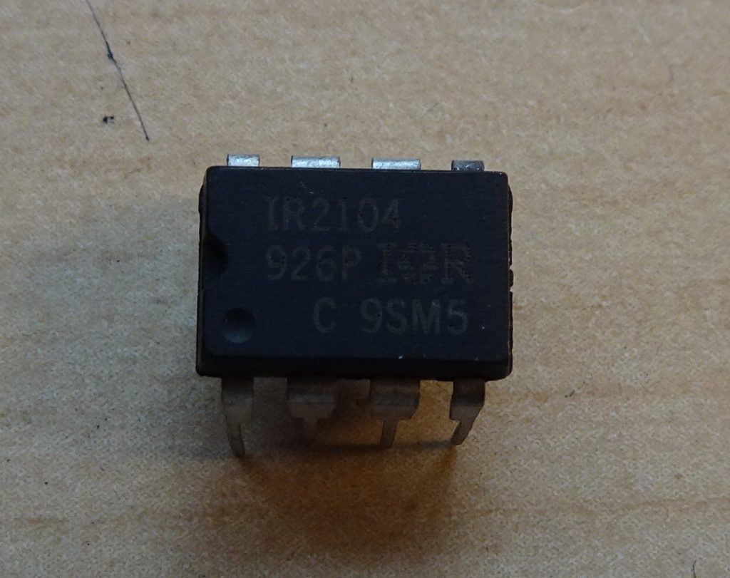
The package looks more-or-less ok, and the text is laser-etched, but the surface finish is not as nice as you’d expect. I rubbed the surface with acetone, and noticed that although the text did not disappear, I picked up quite some black stuff. If we compare the cleaned chip with an untreated one there is a clear difference:
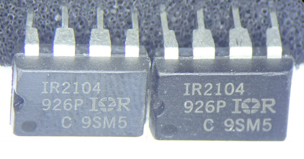
The chip on the left is significantly less black, and because of the uneven surface looks like it was sanded down at some point. This strongly suggests that this is a relabelled chip: someone takes one type of chip, sands down the top layer to remove any labelling, applies a layer of black paint and then prints on a different label. It used to be that this printing was done with ink that you could simply rub off, but as counterfeiters became more sophisticated they started to laser-etch the fake labels, which makes it much harder to tell them apart from real ones.
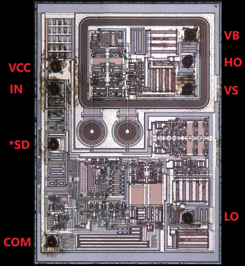
Inside it looks quite all right. We see some relatively simple circuits at the bottom, two large round high-voltage transistors in the middle, and an isolated HV section at the top (surrounded by a thick guard ring).
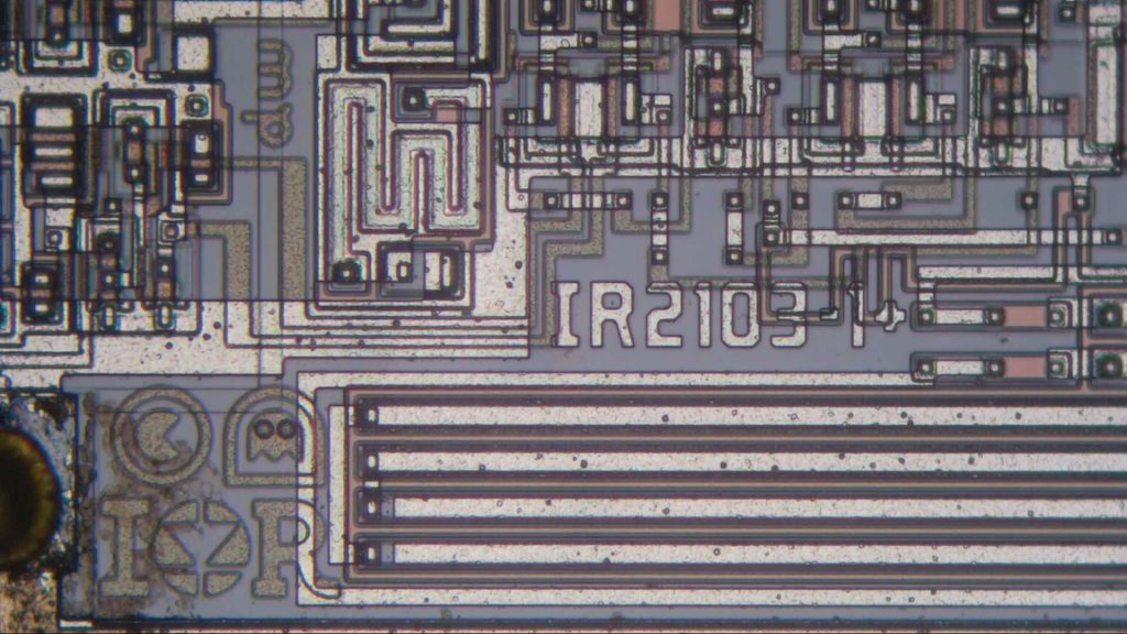
At the bottom there is a chip identifier. This tells us that we’re looking at an IR2103, which is a very similar chip, that differs from the IR2104 in the way the input signals are driven. The IR2104 has one IN pin and one *SD pin. Both outputs follow IN as long as *SD is high. The IR2103 instead has HIN and *LIN pins, which can be used to separately drive the high and low output signals. A quick test of one of the remaining chips shows that it indeed follows this logic.
Another interesting feature is right above the IR logo in the bottom-left corner. Normally a manufacturer would include the copyright symbol © and the mask work symbol Ⓜ. In this case the layout designer decided to modify these symbols a little bit and turned them into Pac-Man and a ghost! This designer might have “dw” or perhaps “mp” as their initials, which they also left on the die.
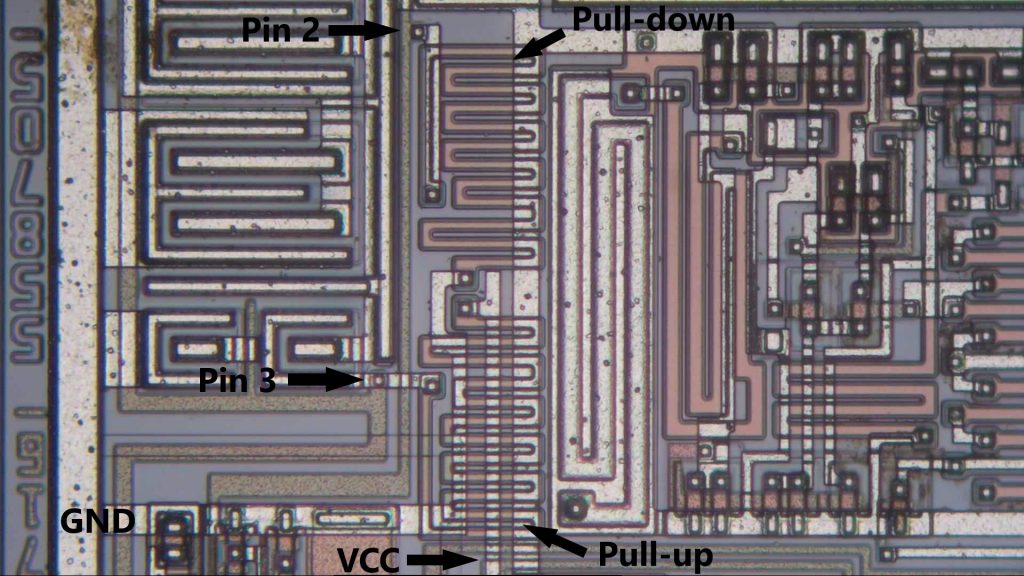
A further circuit-level difference between the IR2103 and IR2104 is that in the ’04 both inputs (pins 2 and 3) have a pull-down resistor to GND, while in the ’03 the *LIN signal (pin 3) has a pull-up to VCC. And if we follow the traces in our suspect chip, we find that while pin 2 has a pull-down, pin 3 has a pull-up resistor. That confirms once more that this is actually an IR2103.
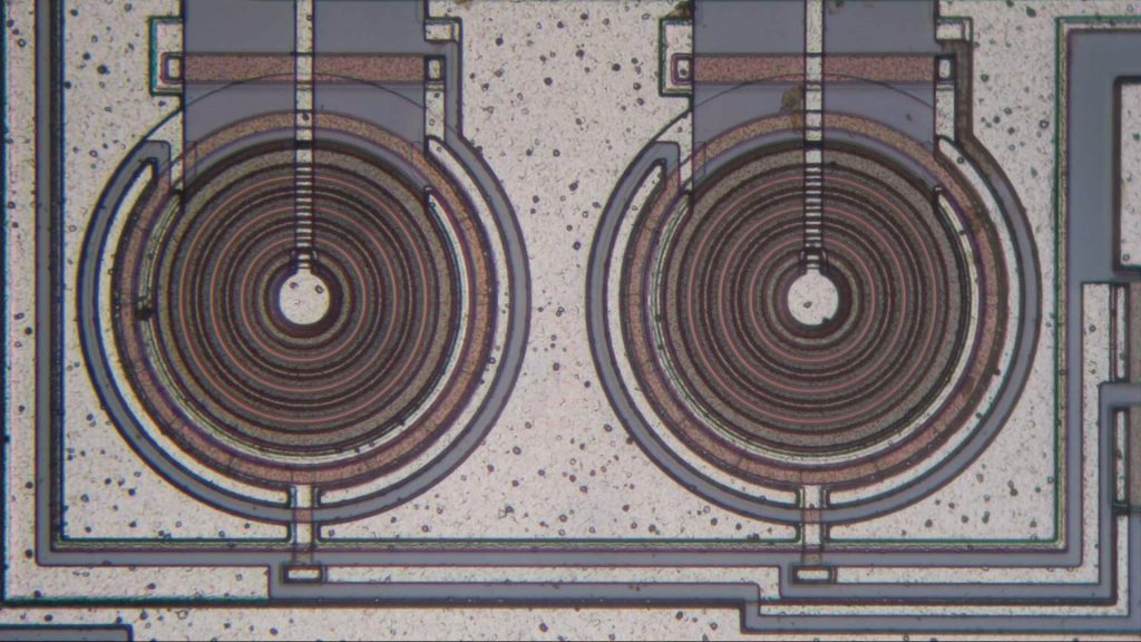
The two high-voltage transistors are of an interesting design. The gate signal comes in at the bottom and seems to be connected to the outermost red ring. The source would then be the outermost ring, which is connected to ground through a poly resistor (the red bar on top). There is also another ring inside the gate ring which is also connected to ground. Perhaps this is a field plate, which drives down the electric field close to the gate to increase the breakdown voltage. Finally, after three rings of some insulation material there’s the drain contact right in the middle.
Overall then, this appears to be a genuine IR2103, which someone re-labelled and then sold as an IR2104. Although this would make a profit (the ’03 sells for about $0.90 in large quantities, while the ’04 is about $1.20), it is rather stupid because the chips are not drop-in replacements, and a circuit designed for one will not work with the other. It makes me wonder why they didn’t simply re-label any other old chip, or even sell empty DIP packages; those would have worked just as well.

My circuit with IR2104 was not working. After reading this post, I changed the inputs to the “IR2104” and found that it was following the logics of IR2103. I bought these from an online store in India. I was shocked. Thank you for your article.
Thank you so much! I was struggling to get outputs assuming my ic was IR2104, but after frying up many arduino’s, I discovered your blog, and found out that the IC was following logics of IR2103. I bought it from a local shop here. I will get the original IC today.
nice article , does it mean i have to match SD to HIN to continue using the fake IR2014?
Maybe, maybe not. Since it’s a fake chip it might follow the logic of an IR2014, an IR2013, or whatever other chip they put in there. The only way to be sure is to buy real ones!