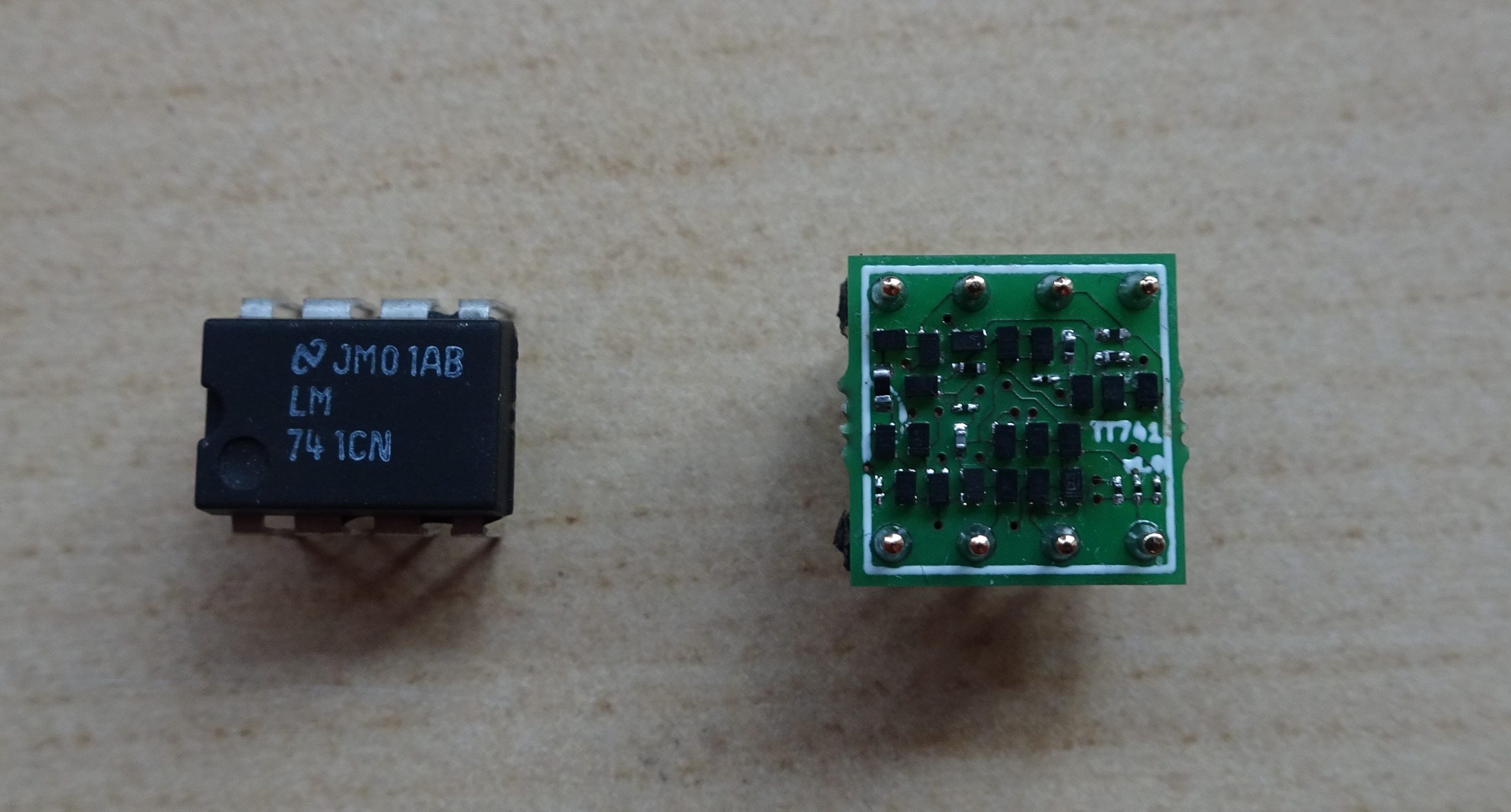
Regular readers of this blog will have noticed that the 741 op amp features quite often. Apparently I’m not the only one with an interest in this venerable amplifier; the Wikipedia page on op amps contains a detailed description of the 741, several books and web sites describe and even celebrate the chip’s history, and you can buy a kit to make a large-size discrete replica from a company called Evil Mad Science Labs. I bought one of these because I thought it looked rather cool.

On the picture above you can see the 741SE compared to an original LM741. I got the SMD version of the kit, although you can also buy one that uses through-hole components and is shaped like a giant DIP package. Still, even the SMD version is enormous compared to the real chip, which got me thinking: would it be possible to make a discrete equivalent of the 741 in a space equivalent to an actual DIP chip?
To start, let’s figure out what components we need to implement the 741. Let’s take a look at the schematic:
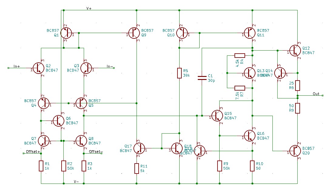
I drew this in KiCAD, based on the schematic shown in National’s datasheet for the LM741. It’s also the same basic schematic used by the 741SE kit, although its designers decided to make a small modification by adding diodes between the input NPNs (Q2/Q3) and the cascode PNPs (Q4/Q5). This is because discrete PNPs have a much lower base-emitter breakdown voltage than the lateral PNPs in the IC, which can cause problems at large input signal swings.
(Actually, the schematic in National’s datasheet is not identical to what’s inside their IC either; as it turns out, there are several varieties of the 741 circuit and what the manufacturers draw in their datasheets does not necessarily correspond to what they produce in their fabs. But that’s something for another article…)
Based on the schematic above, I would need the following:
- 13 NPNs
- 7 PNPs
- 11 resistors
- 1 capacitor
Resitors and capacitors are available in very small sizes. I decided to go for the smallest size commonly available: 01005, which is 0.4 mm long and 0.2 mm wide (and therefore also known as “0402 metric”, but I find that very confusing since there’s also an “0402 imperial” size). A few of the various resistor sizes were not available in 01005 in my favourite webshop, so I bought those in the slightly larger 0201 size (0.6 mm x 0.3 mm). The main bias resistor (R5) can dissipate up to 46 mW, so for that one I had to settle for an 0402 size (1.0 mm x 0.5 mm) which is able to handle this without melting.
Choosing the right transistors was trickier. As you can already tell from the photo above, the SOT23 package used in the 741SE kit is way too large to fit onto a DIP package 20 times. Luckily, it turns out that a much smaller alternative is available: both Nexperia and Diodes Inc make BC847 (NPN) and BC857 (PNP) transistors in SOT883 packages (also called DFN1006-3), which are only 1 mm long and 0.6 mm wide.
The PCB had to accommodate two rows of thin pin headers, to allow it to be plugged into a socket or PCB designed for a DIP-8 package. This meant a total size of 10 mm by 10 mm, and a useful circuit area (after placing the headers) of about 6 mm by 9 mm. Then came the work of placing and routing the PCB. After a few evenings of tweaking, and pushing the design rules to their absolute limits, I had a complete and correct layout. I sent it off to a manufacturing house, and a week later I got a stack of tiny little circuit boards:
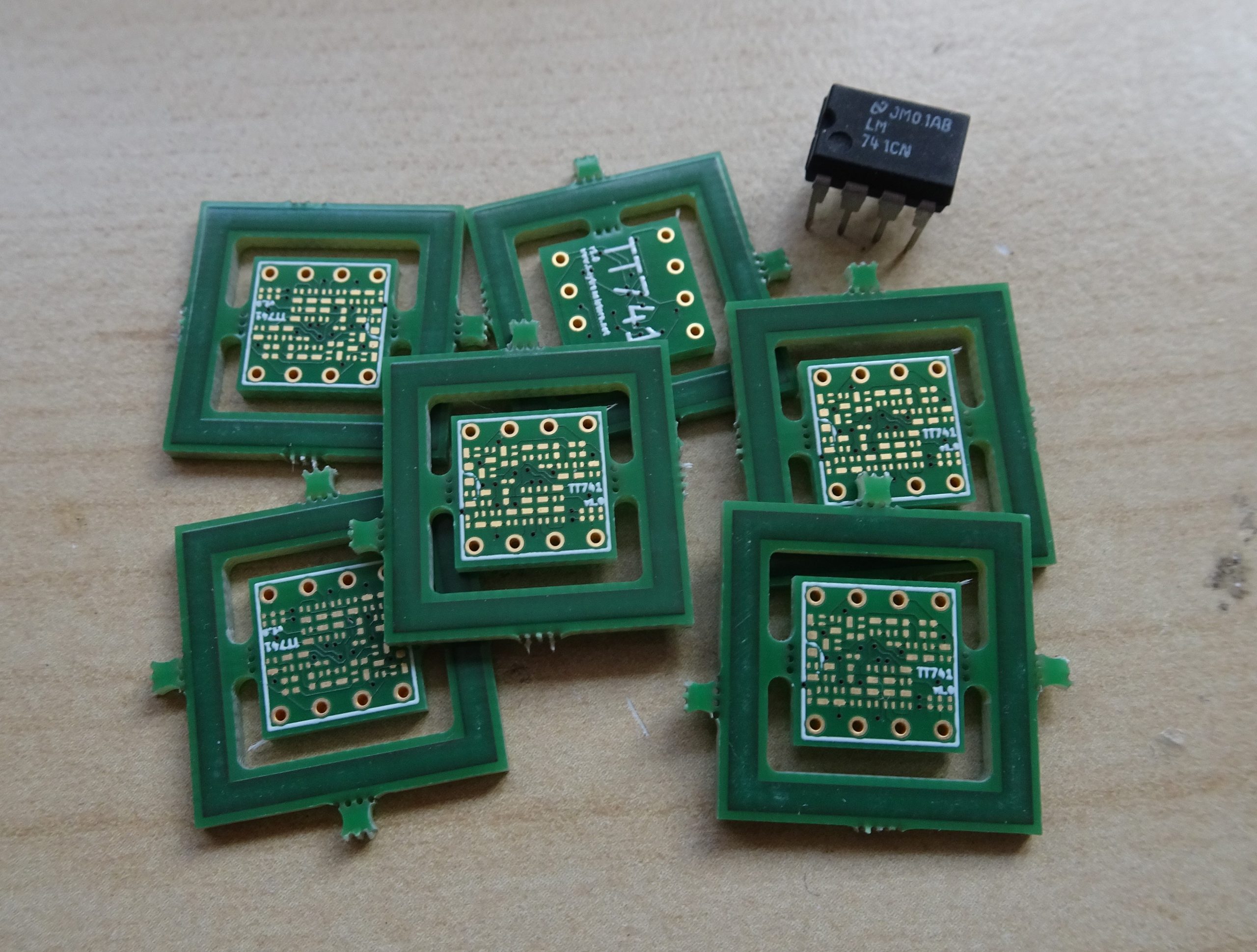
Although their website mentions that all designs should have a minimum linear dimension of 1.5 cm, the friendly folks at Aisler didn’t complain when I submitted my design, and solved the size problem by simply adding a square frame around my board.
Then came the soldering part, which was significantly harder than assembling the 741SE. But using a very sharp soldering tip, very thin solder (0.3 mm), very sharp tweezers and a good microscope it took just a couple of hours to assemble a TT741. You can see the result below.
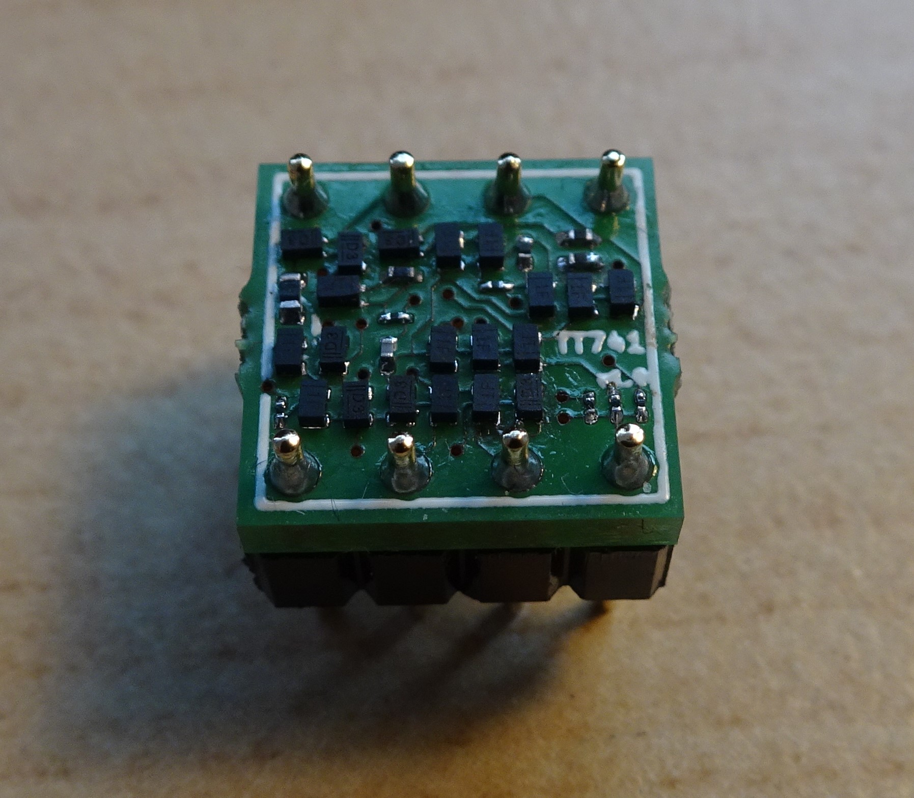
It’s nice and compact, and actually feels sturdier than a real DIP package: the pins don’t bend as easily. Compared to our LM741 it does look a bit chubby, but it is plug-in compatible:
Of course, this exercise would be rather pointless if the resulting circuit didn’t work. So I made a simple test board, connecting the chip in unity-gain configuration and loading it with 2 kΩ in parallel with 100 pF. Driving a 1 V square wave at 10 kHz at the input shows a reasonably good square wave at the output.
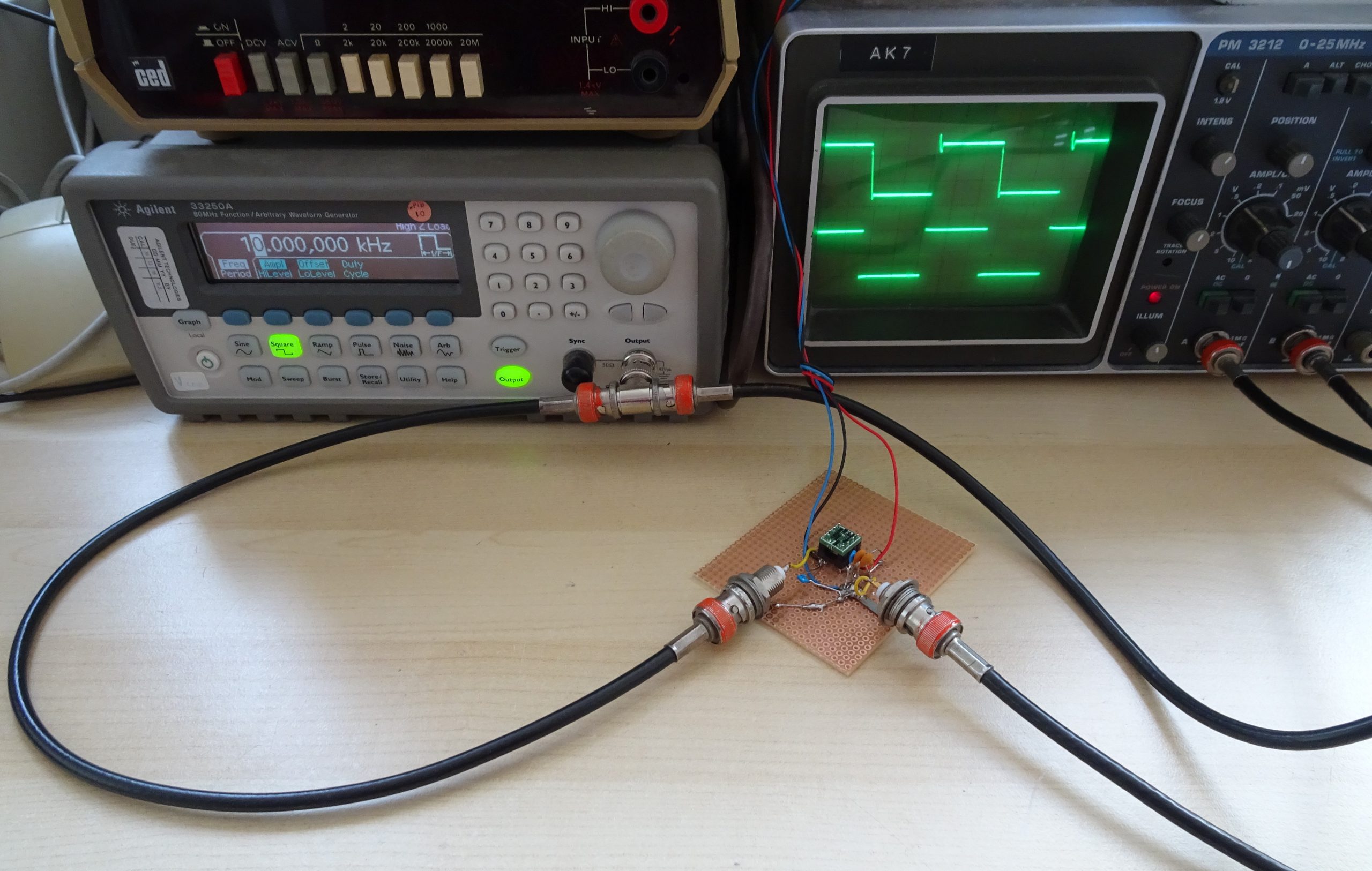
Zooming in on the falling edge of the square wave we find that the TT741 has a slew rate of about 0.5 V/us, like the LM741. There is a bit of overshoot at the rising edge, which is most likely caused by the absence of some parasitic capacitances to ground that are present in the IC. The large (actually, enormous) 741SE board shows a similar behaviour.
Overall, this little project shows that it’s not just ICs that have got smaller over the years; with today’s discrete components it’s possible to make circuits just as small as IC designers could make them 50 years ago. Even discrete transistors can now properly be called “tiny”!