When you build a PC, there’s a specific place for each component: the motherboard goes in the back of the case, the CPU and RAM plug into their designated slots, hard drives and other storage devices go in drive bays, and expansion cards plug into their slots on the motherboard. What should you do then, if you’re out of storage but have no more 3.5″ or 5.25″ drive bays left? Back in the 1980s, a company called Plus Development came up with a neat solution: a hard drive integrated onto an expansion card.
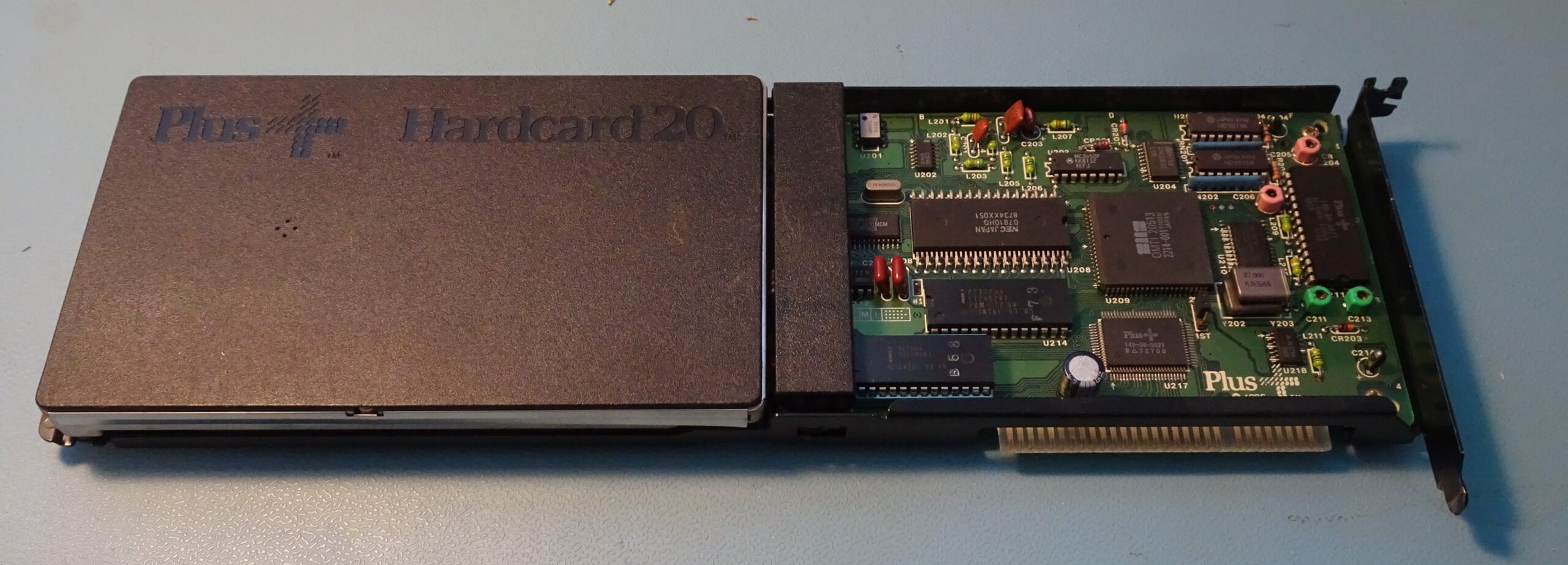
This one, made in 1987, had been sitting in my junk box for years. I found it somewhere years ago, tried it, couldn’t get it to work, and forgot about it. Today however, I’ll try to get it to running again and find out if there’s still any data inside. Its total capacity is 20 MB, and it connects to a PC through an 8-bit ISA bus.
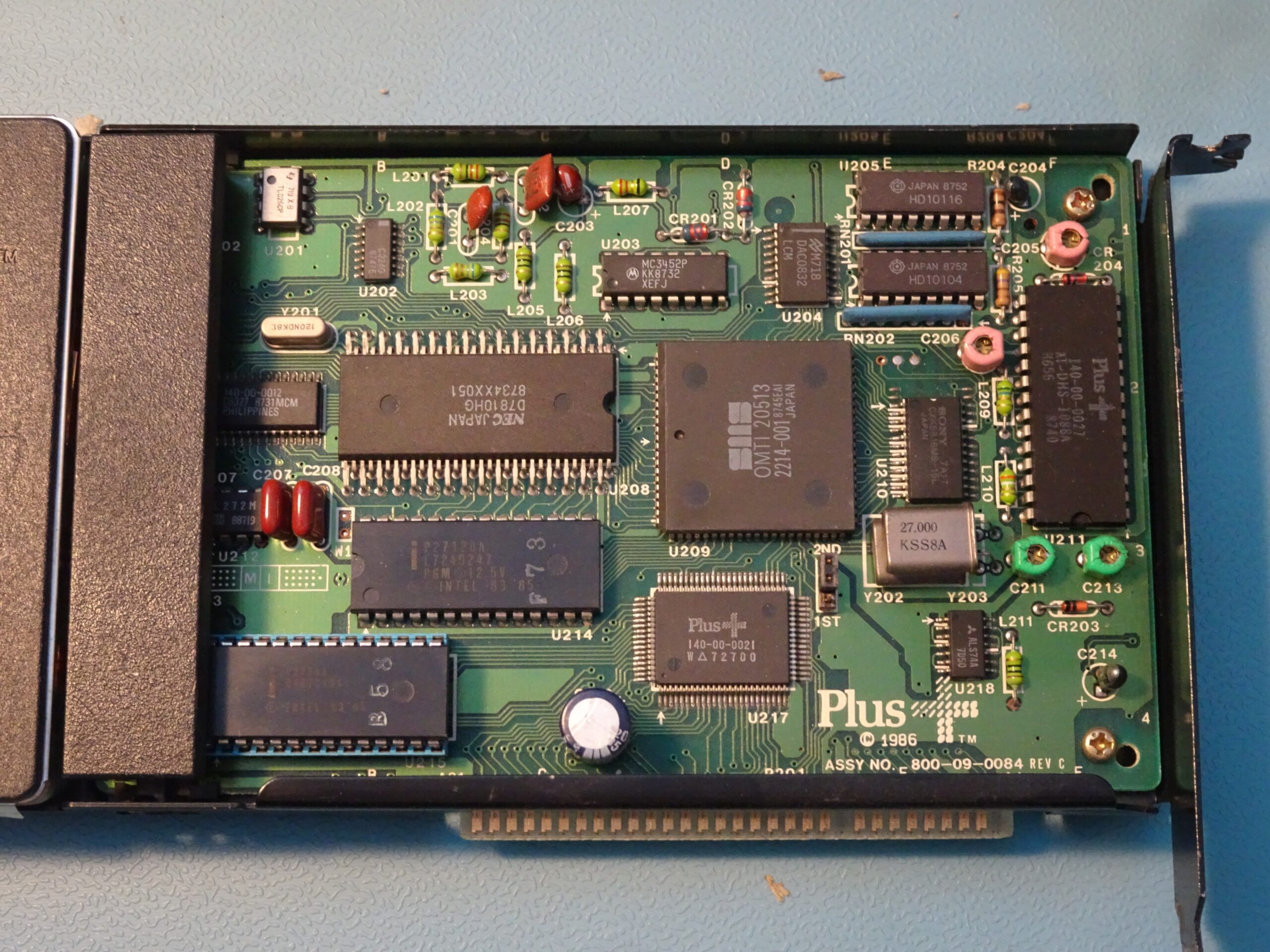
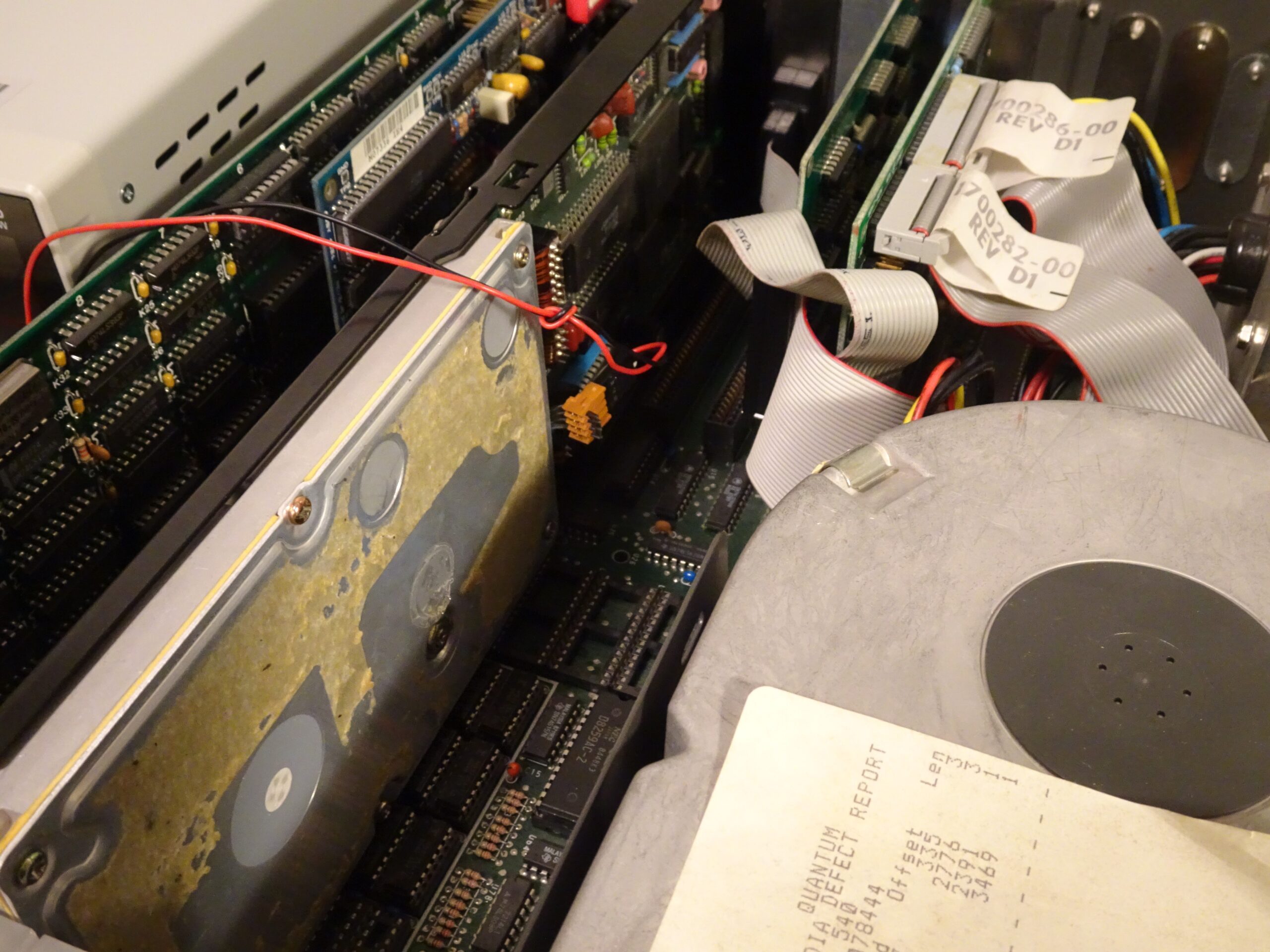
The neat thing about a Hardcard is that it has a complete disk controller integrated inside, so it’s really a plug and play solution. There’s a big metal bracket around the outside to give it enough rigidity and prevent the heavy hard drive on the left from wobbling or putting too much stress on the motherboard. The design of this specific bracket is a bit unfortunate, however: it sits tightly around the ISA edge connector and makes it impossible to plug the card into a 16-bit ISA slot. Luckily, I’ve got an old XT sitting around in my lab that I can plug it into. There’s a jumper to set the card to be either the first or the second hard drive present in the system. I’ve set it to “2ND” because I’ve already got a hard drive in my XT.

This is what happened when I installed the Hardcard and booted the computer. The blinking cursor on the left is from the XT’s BIOS, while the blinking “+” sign on the right is from the Hardcard’s ROM. A fully functioning Hardcard uses the “+” in the top right corner to show disk activity, because there’s no drive light on a fully internal hard drive (drive activity indicators were apparently considered essential in the ’80s; today, no one cares for them). It’s always there when using the DOS command line, although it can be disabled through a utility program included with the Hardcard.
My Hardcard was not fully functional, however: the Plus sign kept flashing for about a minute, after which it (very briefly) showed an error message.
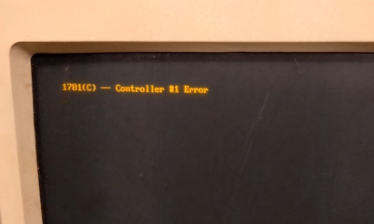
Error 1701 is kind of meaningless: it just tells you that something’s wrong with the hard drive and it’s not working. Indeed, after the computer booted into MS-DOS (on the primary hard drive) it didn’t show a second drive to be present. For some reason the computer became really sluggish as well when the Hardcard was plugged in. Time to figure out what’s wrong!
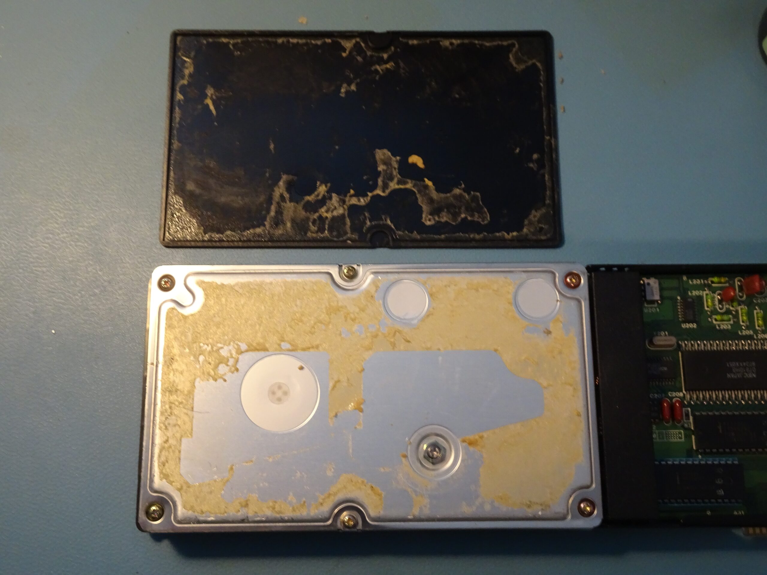
To get into the drive, we first need to remove the decorative cover, which is glued into place. It took me quite some time with several prying tools, but I did manage to get the cover off in one piece. The hard drive unit is held shut by six screws and one nut.
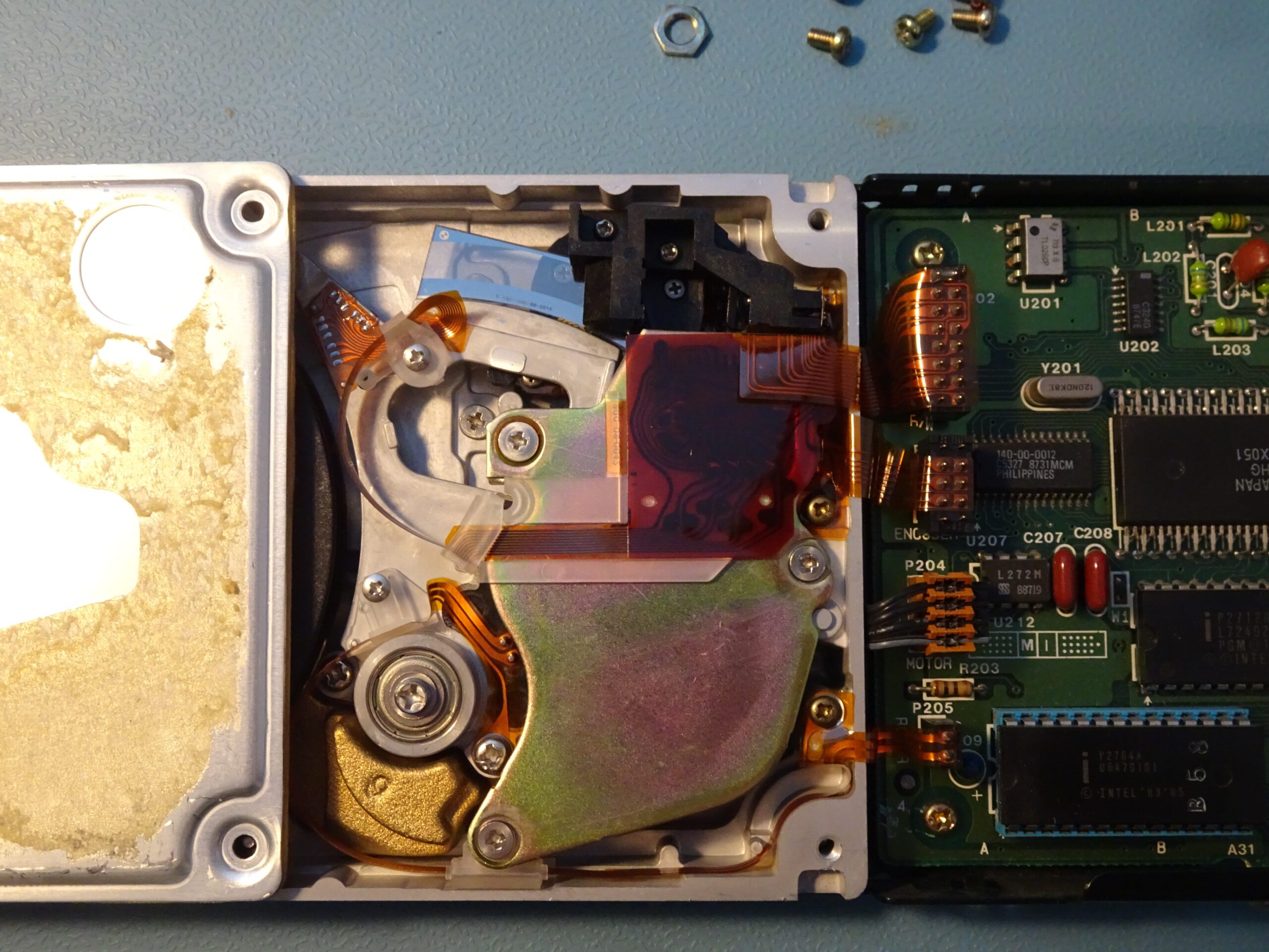
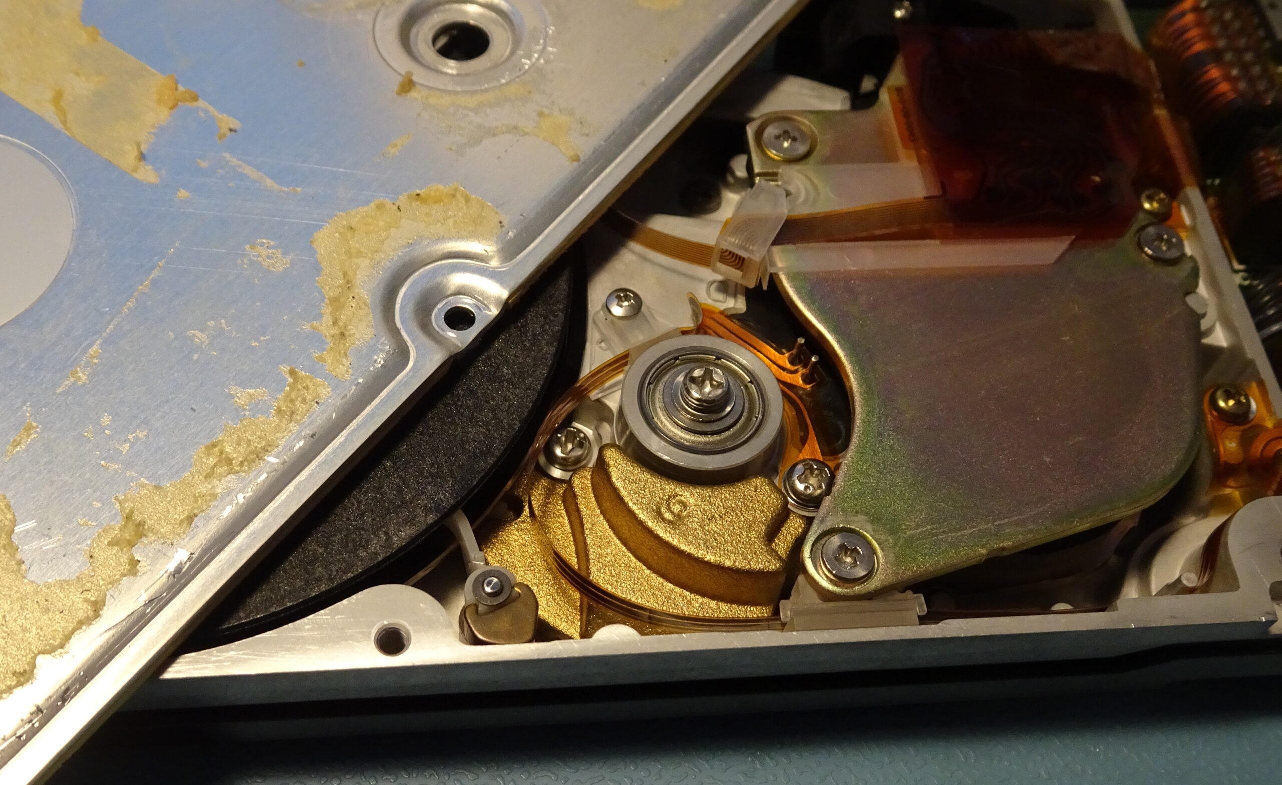
Inside, we find the platter on the left, and the head actuation mechanism on the right. There is one dual-sided data platter on the bottom of the drive’s spindle and one plastic dummy platter on top. I would guess the drive was set up like this so they could use the same basic hardware for the 20 MB and 40 MB versions, with the larger capacity drive having two data platters and an extra set of read/write heads.
The actuation mechanism is interesting, because it is a very early example of voice coil technology. Hard drives in the early ’80s typically used a stepper motor to move the read heads, which is simple to implement but slow and difficult to scale to a very small track pitch. A voice coil consists of a flat coil of wire which moves inside a strong magnetic field. This setup can move way faster than a stepper motor, but needs additional circuitry to align the heads with the magnetic tracks on the disk, since unlike a stepper motor, a voice coil can move smoothly to any position.
The drive we’re looking at today uses Quantum’s Light Positioning System (LPS) to move the coil to predetermined positions. A shiny piece of glass, visible at the top, has a number of fine lines printed on it and moves with the head assembly. An optical sensor, inside the black plastic structure, detects the lines on the glass and drives the voice coil’s current in order to fix it in a specific position. Modern drives (from the ’90s onward) still use a voice coil, but drive it based on signals picked up by the read heads.
Normally, it’s a really bad idea to open up a hard drive because the heads and platters are extremely sensitive to dust. Professional hard drive technicians will only open up a drive inside a cleanroom, because even a tiny speck of dust can get caught between the head and the platter and cause serious damage. This drive is only 20 MB though, which is barely ten times the data density of a floppy disk, so it isn’t nearly as sensitive as a modern multi-terabyte drive. Still, I’m keeping the cover on as much as possible and avoid touching anything unless I have to.
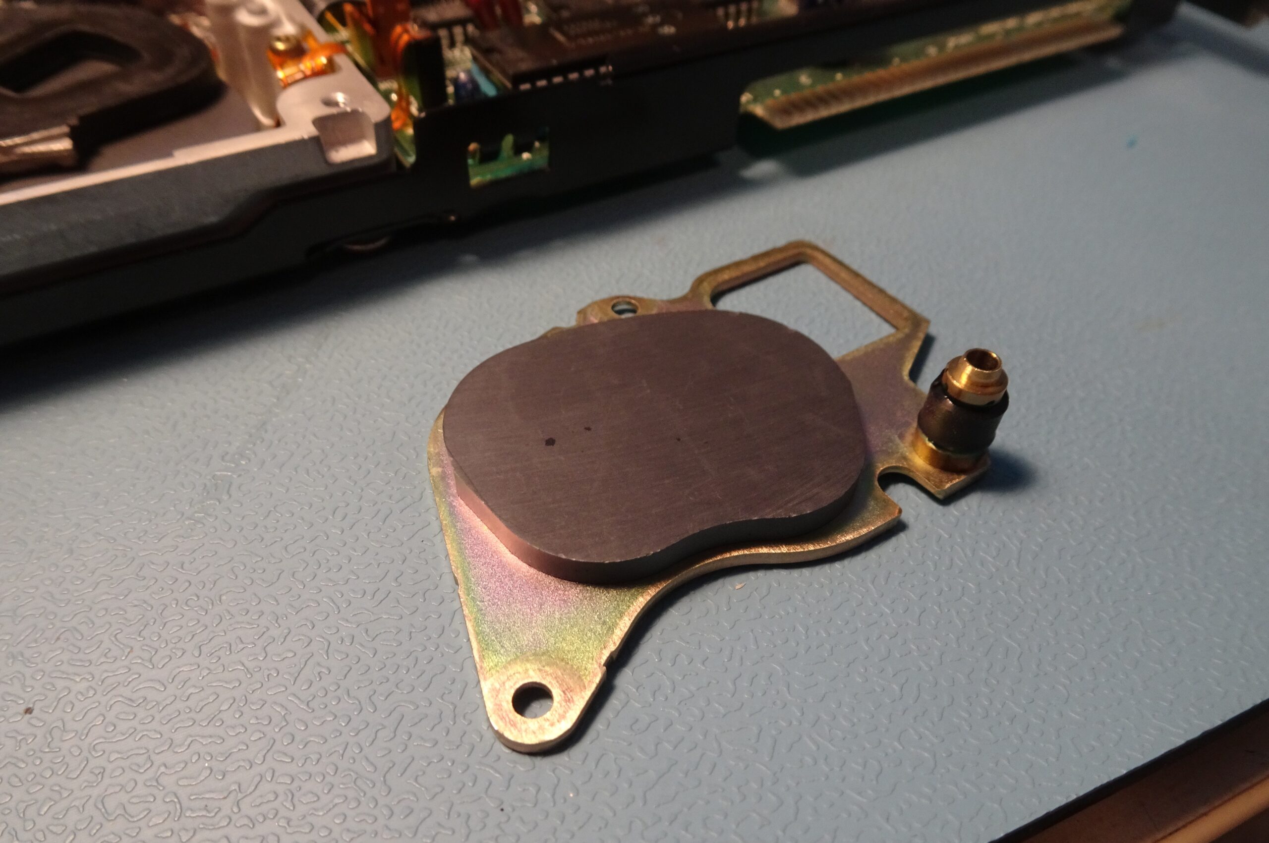
If we remove the top magnet (exposing the voice coil, encased in black plastic, in the top left of the image), we can already spot some trouble. The black cylinder on the right edge of the magnet is a bump stop which marks the limits of movement of the head assembly. It’s made of a type of rubber that disintegrates over time and turns into a gooey mess to which the head assembly sticks. This is a very common failure mode for Quantum hard drives of this era.
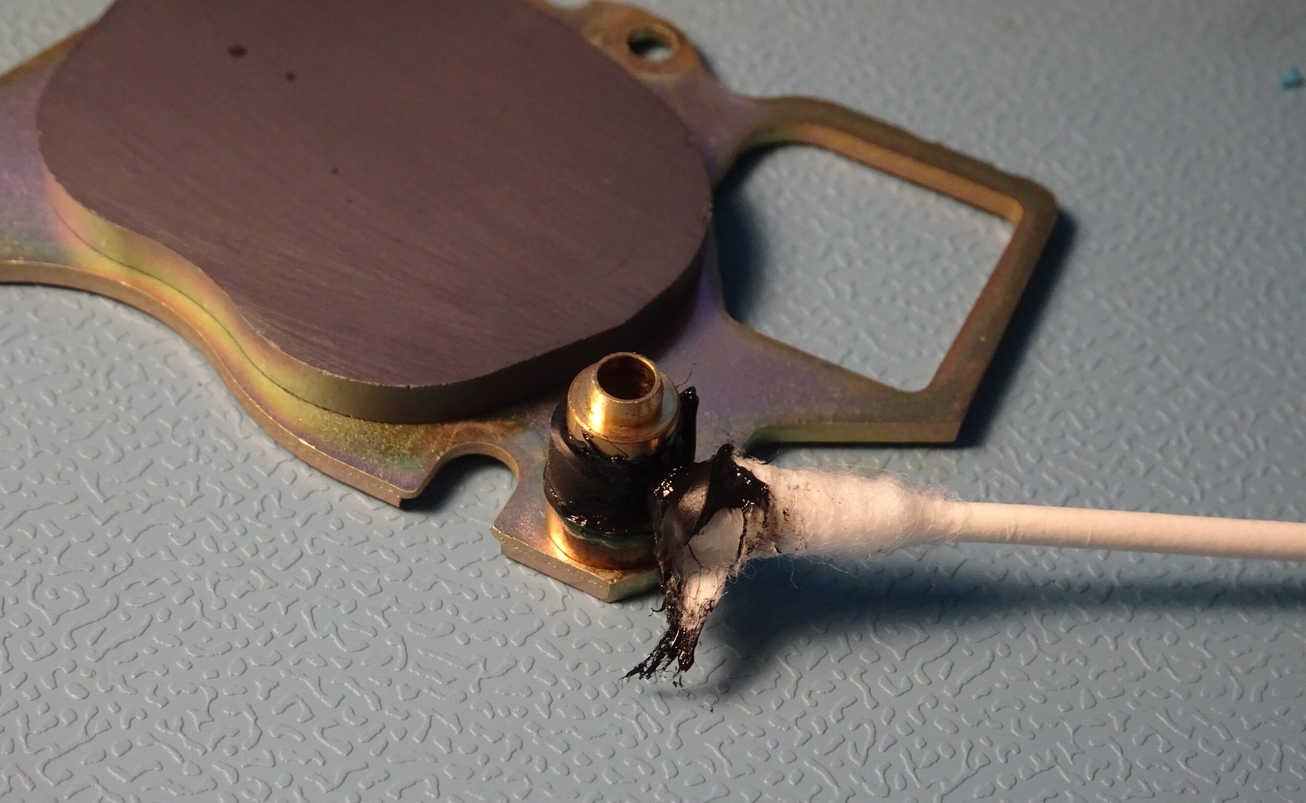
The rubber has disintegrated so far that it’s really not solid anymore: I can actually wipe it off using a cotton bud. The goo dissolves very well in acetone, so I used that to clean off the last remnants.
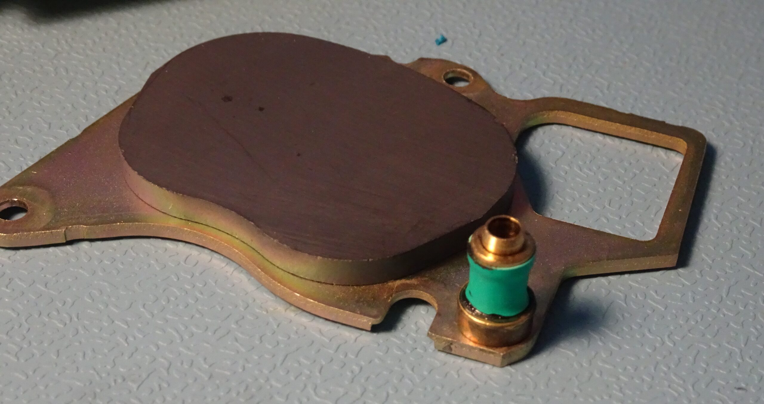
I used a piece of heat-shrink tubing to make a replacement bump stop. The drive would probably work fine even without one, but it’s an easy thing to do.
The head still wouldn’t move however, because the head lock was still in place. There’s a thin plastic strip extending between the platters, which is spring-loaded into place. Once the disk spins up, the resulting air currents move the strip backwards, which unlocks the head assembly. When the disk powers down, the heads move to the parking area and are locked in place, preventing damage to the disks when the drive is transported.
Speaking of spinning up: the drive still wasn’t doing that. At first, I thought this was because it detected the heads being stuck, but I now realised this couldn’t be the case: the heads can only start moving after the disk has spun up, so it should start by spinning up in any case.
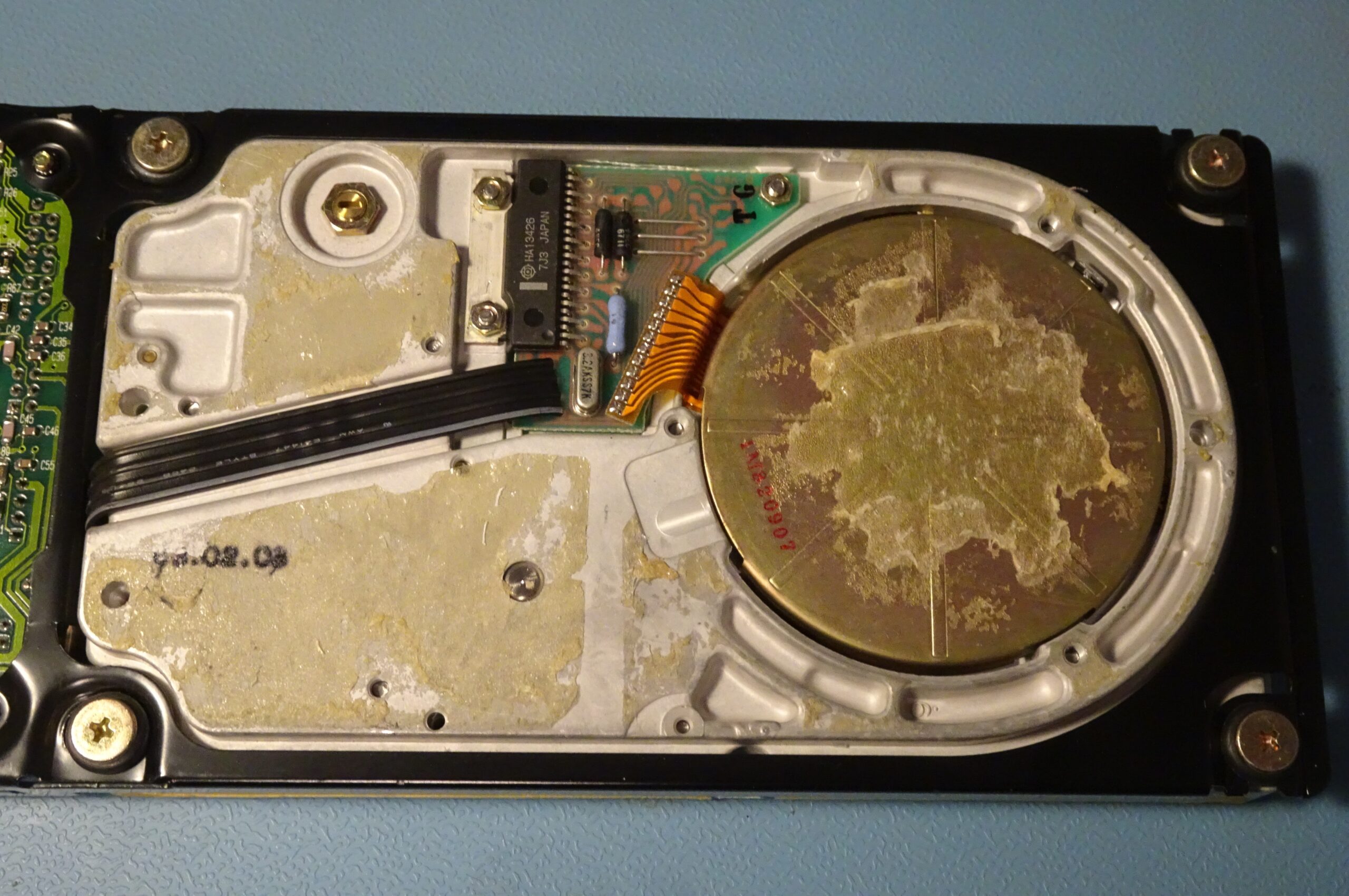
This means something may be wrong with the spindle motor system, located on the bottom of the drive. There was another plastic cover glued over it, requiring another prying session to get it off. Under the cover we find a small driver PCB which connects to the drive motor through a flexible flatcable.
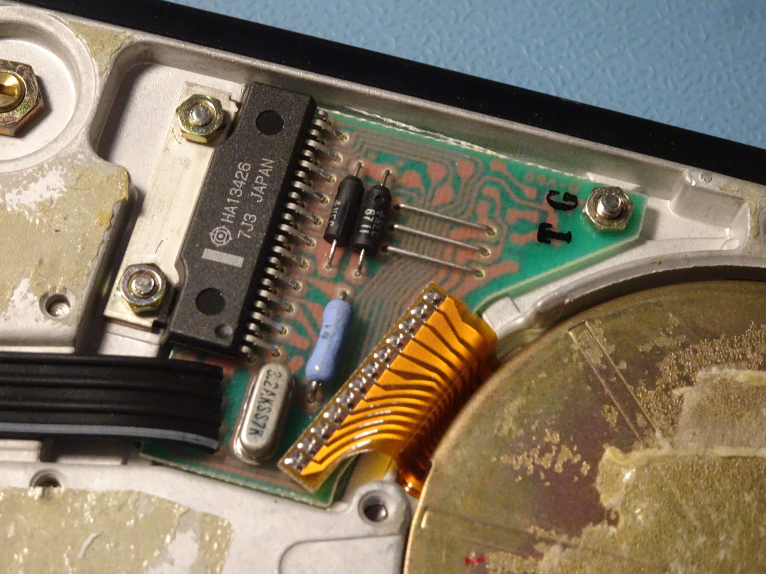
The PCB holds a Hitachi HA13426, which is a motor driver specifically designed for three-phase brushless hard drive motors. It has outputs for driving three coils and inputs for Hall sensors, which allow it to very accurately control the motor’s speed.
The neat thing about this board is that it’s entirely self-contained: if you apply 12 V to it, it will spin up the disk by itself. Pins 3 and 4 of the black flatcable are ground and +12 V, respectively, so I hooked those up to a bench power supply.
The disk then made one or two attempts at spinning. I tried helping it along by manually spinning the disk (which was made very easy by having a plastic dummy disk), but to no avail.
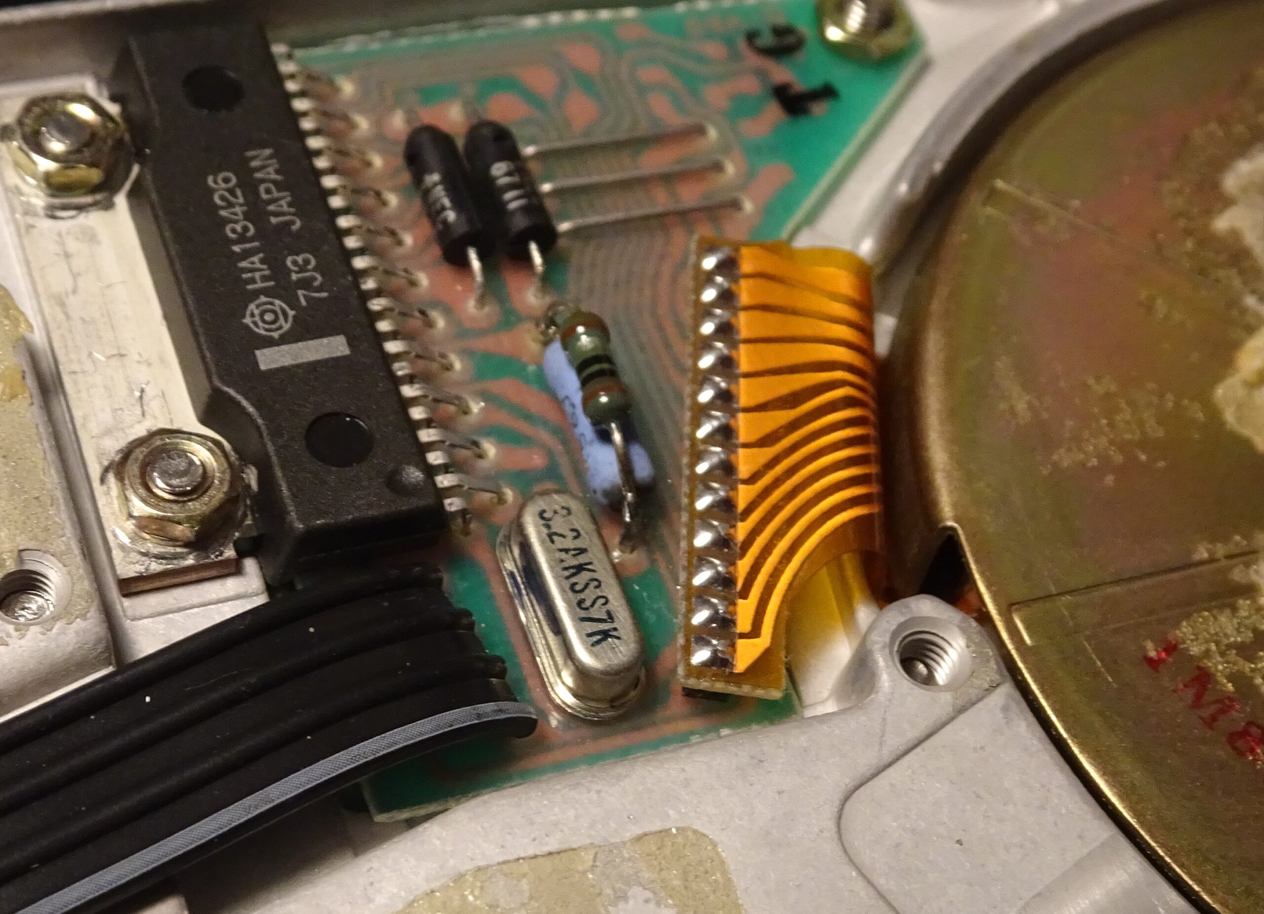
According to the datasheet, a resistor connected between pin 7 and ground determines the maximum drive current. The blue resistor on this PCB has a value of about 0.5 Ω, which results in a maximum current of 1 A. I added another 1 Ω in parallel to increase the current by 50%. I also turned up the voltage to 13.5 V. This finally convinced the motor to start spinning. Most likely the bearing had seized up after sitting still for about three decades. Apparently, it’s also possible to clean and lubricate the bearings, but this requires a complete disassembly of the platters and heads, which is a very risky operation.
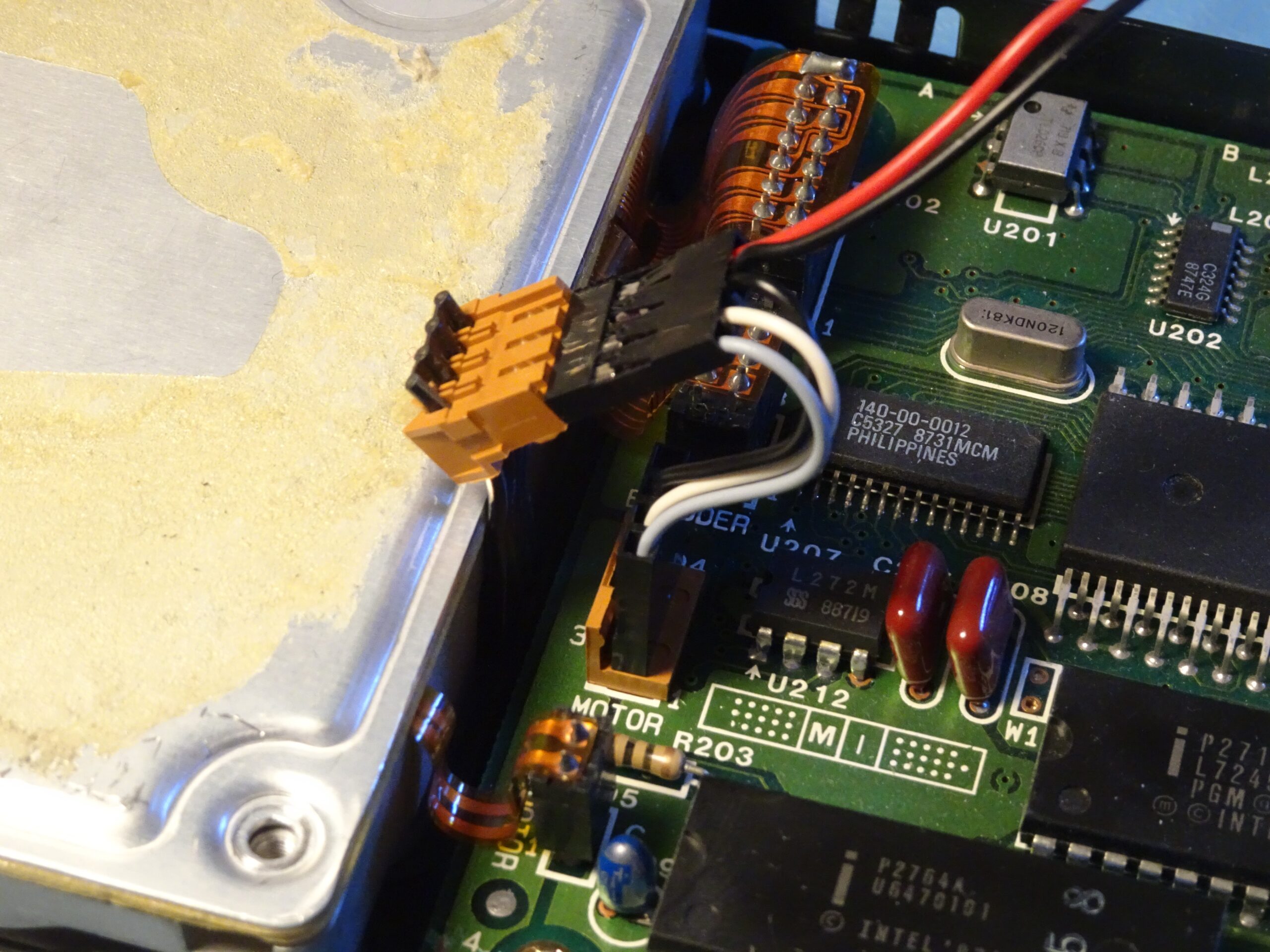
The XT’s PSU doesn’t output 13.5 V, however. I wonder if it even manages to output 12 V when trying to spin up two hard drives, so to help it a bit I made this special connector to externally power the Hardcard’s drive motor. This way I could try to spin up the drive before booting the computer, and also relieve the XT’s PSU from having to deliver all that current.
This system worked very well, although I still got the controller error the first few times I tried to boot the system. Then, suddenly, the computer booted normally and allowed me to access the D: drive. Perhaps the lubricant in the bearing needed a while to warm up and allow the drive speed to stabilise enough for the controller to be able to read the data.
As soon as it was all working, I fired up the DOS Lan Manager client, mapped a network drive, and began to dump the data right away, because you never know how long an old, worn-out drive will last.
As it turns out, this disk used to belong to someone named Simon who worked in the finance department of a university back in 1991 and 1992. The drive contains PC-DOS 3.2 along with a standard supply of software you’d expect to find on an office PC in those days: WordPerfect 5.1, dBASE III, and Lotus Symphony 2.0, plus several documents that Simon worked on, like letters and invoices. Nothing too exciting, but still an interesting look into a random office PC from more than thirty years ago.

Another interesting thing that happened during this project was that an EMI suppression capacitor in the XT’s monitor failed. I noticed this when I returned to my lab after a few hours, having accidentally left the monitor plugged in and turned on. This shouldn’t normally be a problem, but older power supplies sometimes have X2 capacitors like this one that can suddenly fail. At least it failed gracefully without catching fire, as safety capacitors are supposed to do, so in that sense it performed well. Unfortunately, the liquid it releases in the process has a horrible smell and ends up everywhere on the circuit board.
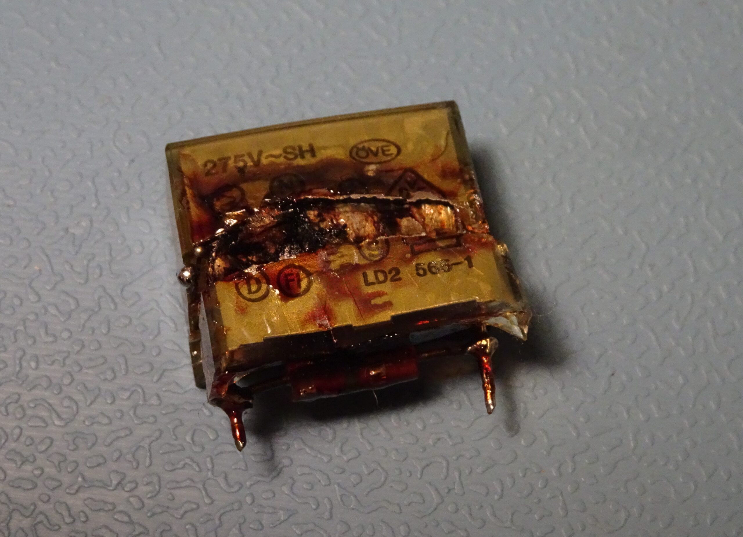
This is what a Rifa PMZ2050MC, a 220 nF X2 capacitor, looks like after it’s let out the magic smoke. This one also had a 1.2 MΩ bleeder resistor connected in parallel. These old Rifas are notorious for randomly blowing up, so you might want to replace any you find in old gear as a precaution.