Commodore 64 power supply with TPS543021

The Commodore 64 needs no introduction: an icon of 1980s computing and one of the most-produced computers in history. But successful as the computer itself might have been, its accompanying power supply has always had a reputation for shoddy quality, with many failing even in Commodore’s heyday. If they would just fail by shutting down, that would be one thing, but unfortunately, these PSUs often fail in the worst possible way: by outputting 6 or 7 volts on their +5 V rail, thereby blowing up many hard-to-find chips inside the computer.

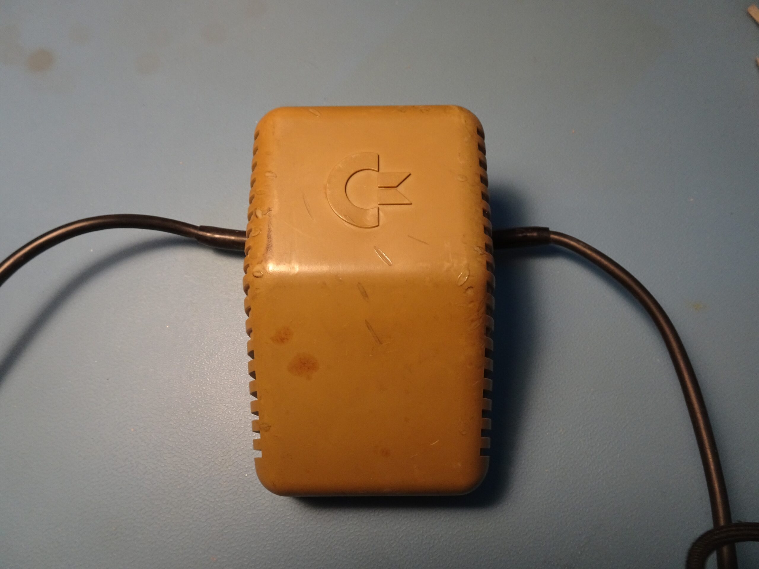
This is the one that came with my C64. It still outputs a neat 5.2 V, but given its reputation I don’t want to risk my Commodore’s guts by using it. Instead, I decided to take it apart and try to improve it. There aren’t any screws on this case, but the bottom eventually comes off if you keep prying on all sides and work it off vertically.

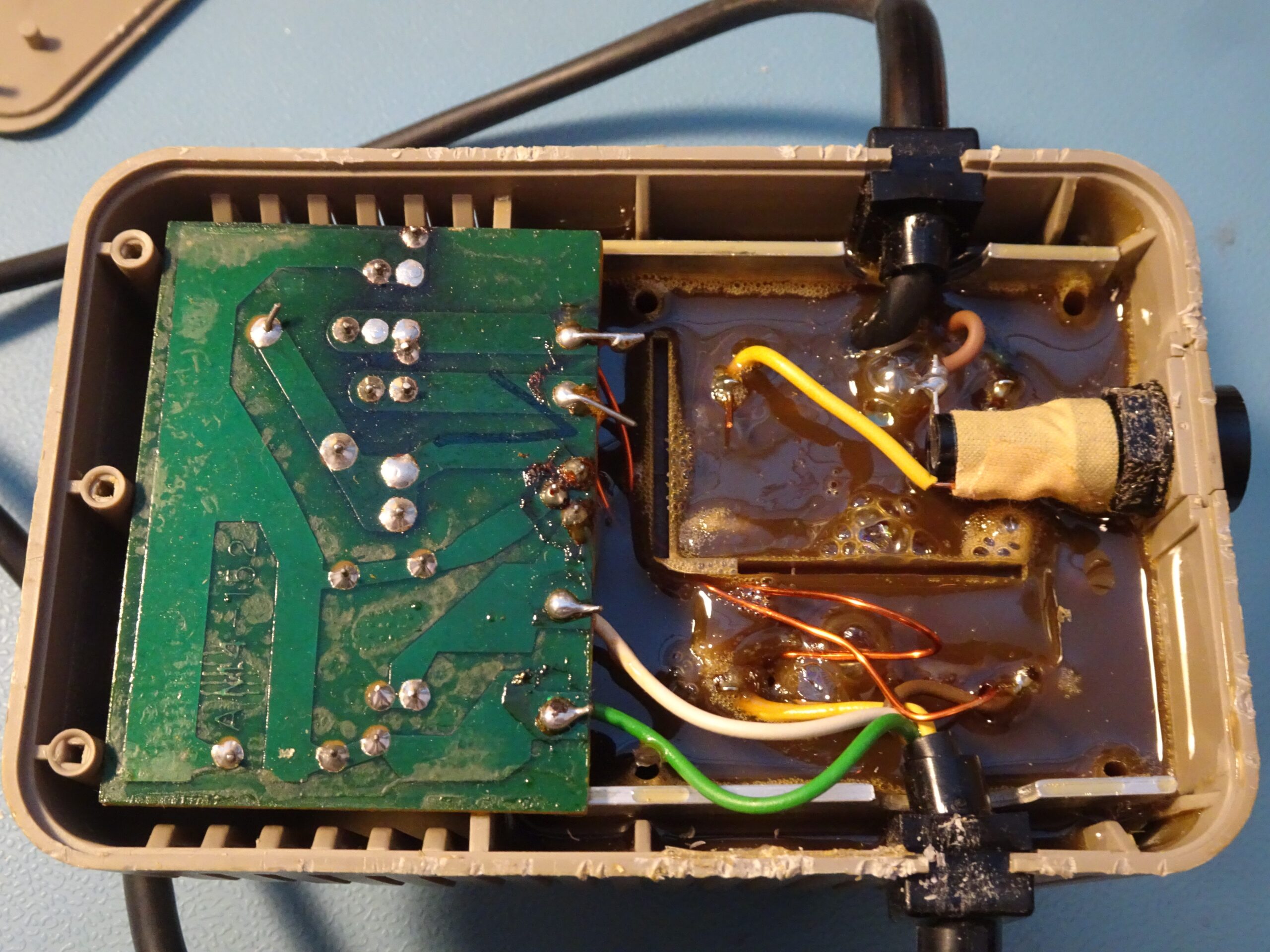
Like most small computers in the 1980s, the Commodore 64 uses a linear power supply. The design is pretty basic: a transformer with two 9 V output windings, of which one goes directly to the computer, and the other connects to the circuit board on the left. The transformer is completely enclosed in potting compound along with the voltage regulator (you can see its three pins in the middle of the board’s right edge).

Continue reading

Plus Hardcard repair

When you build a PC, there’s a specific place for each component: the motherboard goes in the back of the case, the CPU and RAM plug into their designated slots, hard drives and other storage devices go in drive bays, and expansion cards plug into their slots on the motherboard. What should you do then, if you’re out of storage but have no more 3.5″ or 5.25″ drive bays left? Back in the 1980s, a company called Plus Development came up with a neat solution: a hard drive integrated onto an expansion card.

This one, made in 1987, had been sitting in my junk box for years. I found it somewhere years ago, tried it, couldn’t get it to work, and forgot about it. Today however, I’ll try to get it to running again and find out if there’s still any data inside. Its total capacity is 20 MB, and it connects to a PC through an 8-bit ISA bus.

Continue reading

TT555 Soldering Kit now available on Tindie!

Probably the most-viewed post on this blog so far has been my project to construct a discrete-transistor replica of the 555 timer IC. I’m pleased to report that, due to popular demand, the TT555 is now available in kit form!

This is your chance to prove that you’re a real SMD soldering expert: to assemble it, you need to place 43 components onto a 10×10 mm2 PCB, pick and place 01005 size resistors (0.4×0.2 mm2), and solder DFN-1006-3 packages (1.0×0.6 mm2). A microscope, sharp tweezers and a fine-tipped soldering iron are essential tools to complete this project.

Please click here to find the TT555 on Tindie!

Continue reading

The TT555: a discrete 555 timer plug-in replacement

After dissecting a whole batch of 555 timer ICs I thought it would be an interesting project to make a working copy of the 555’s internal circuit out of discrete components, in the same physical space as the original IC. I’ve done this before with the 741 opamp, and the steps are similar. First, I drew the schematic in KiCAD:

I used the original circuit as designed by Hans Camenzind, as a tribute to his design but also because it uses the smallest number of transistors among all different designs I found while dissecting the various 555 ICs. Discrete transistors are larger than discrete resistors, so the original design saves space compared to newer versions that include several more transistors. Note that it’s the opposite situation when you’re designing an actual IC: integrated resistors are usually the largest parts in your layout.

Continue reading

The TT741: a discrete plug-in 741 replacement

Regular readers of this blog will have noticed that the 741 op amp features quite often. Apparently I’m not the only one with an interest in this venerable amplifier; the Wikipedia page on op amps contains a detailed description of the 741, several books and web sites describe and even celebrate the chip’s history, and you can buy a kit to make a large-size discrete replica from a company called Evil Mad Science Labs. I bought one of these because I thought it looked rather cool.

On the picture above you can see the 741SE compared to an original LM741. I got the SMD version of the kit, although you can also buy one that uses through-hole components and is shaped like a giant DIP package. Still, even the SMD version is enormous compared to the real chip, which got me thinking: would it be possible to make a discrete equivalent of the 741 in a space equivalent to an actual DIP chip?

Continue reading