The RCWL-0515 is a little PCB that can be used as a motion sensor, similar in usage to passive infrared (PIR) sensors. This way you can make a light come on when you enter a room, or sound an alarm when the cat’s waiting at the door.
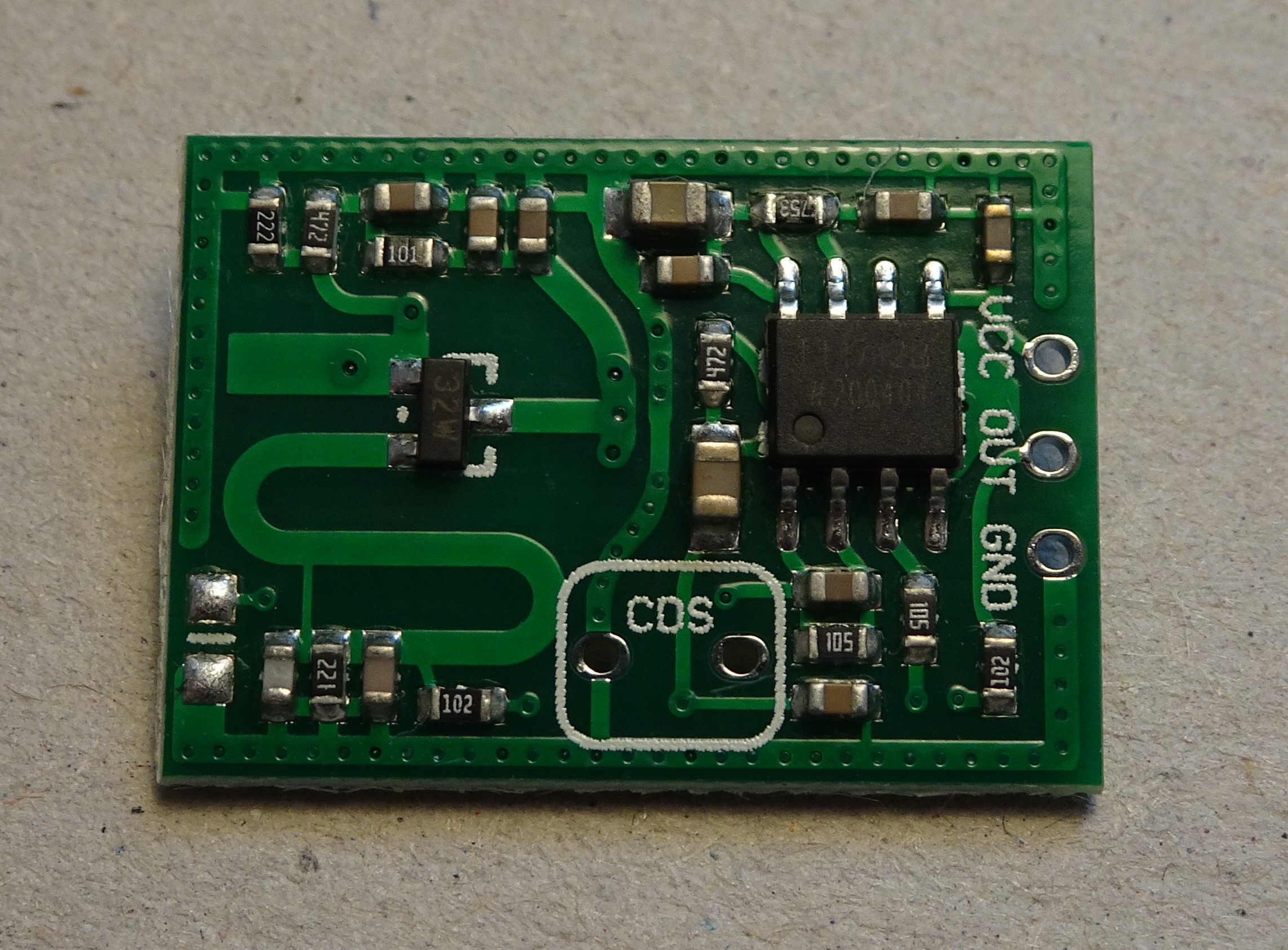
I bought a couple of these things online for €1.15 each, which makes you wonder quite how they can make something like this so cheaply. It contains one IC labelled “TT1712B”, one transistor labelled “32W” and a bunch of resistors and capacitors. The IC is some custom part for this purpose (I could find no information on it whatsoever), while the transistor is a BFR520[1]https://www.nxp.com/part/BFR520#/, a 9 GHz NPN transistor originally made by NXP but in this case probably by some unknown copycat manufacturer (given that NXP discontinued it in 2016).
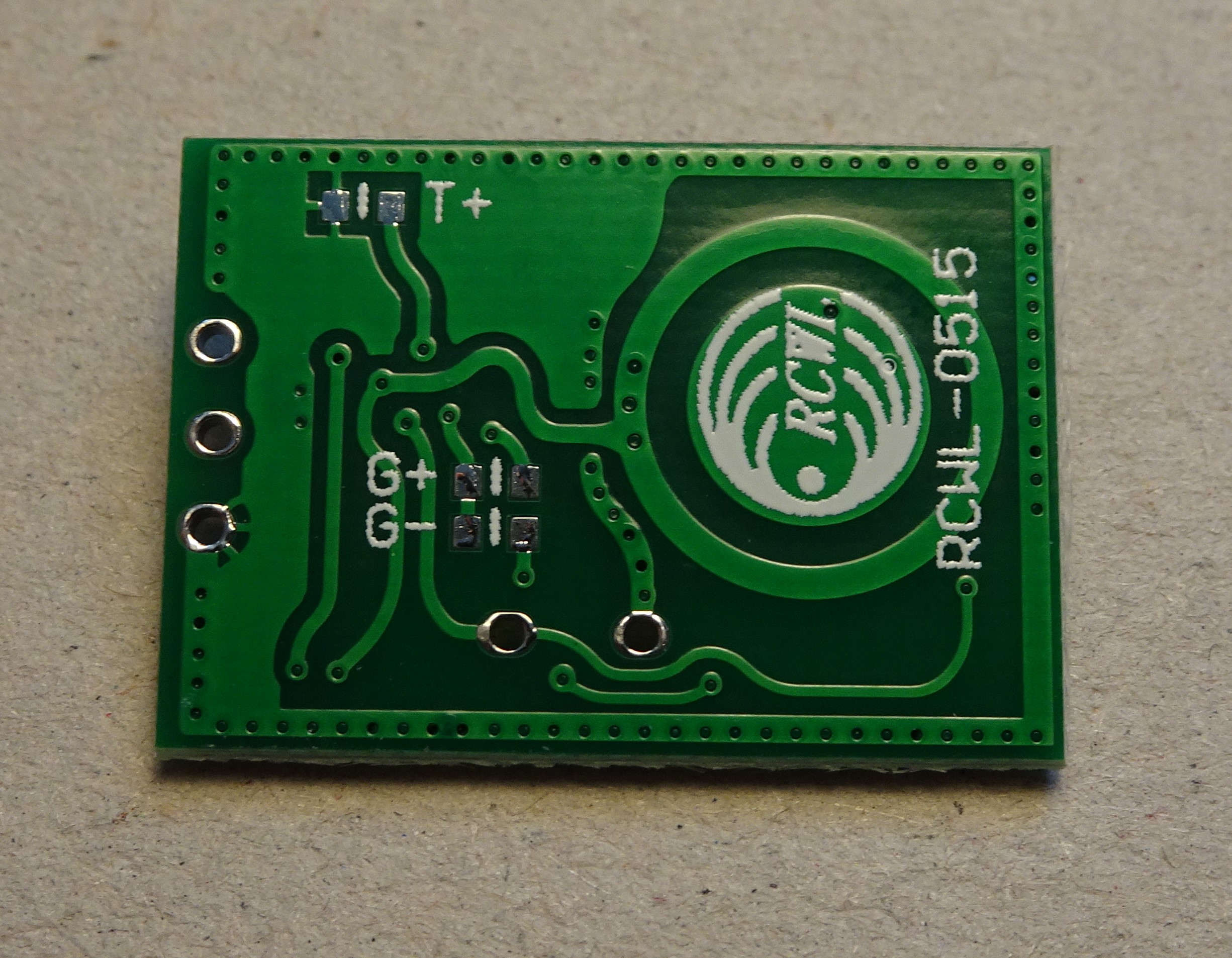
These PCBs are sold under a variety of names, often including the words “Radar”, “Doppler”, “Microwave” and “Induction”. It remains unclear who made it: it is available at a number of online shops, but I haven’t been able to track down who “RCWL” are. There is apparently also a similar PCB named RCWL-0516 which is reviewed on many other websites[2]https://github.com/jdesbonnet/RCWL-0516/, but I’ve not been able to find much information on the ‘0515.

This is the closest thing to a datasheet I could find. Note that there is no mention of who manufactured it! Someone, somewhere, put a lot of effort into designing this circuit, testing it under various circumstances, setting up a production line, buying parts, soldering, packaging and selling the PCBs, but did not bother to announce any of this to the world. How is that even possible? There is a company called RC Wulian[3]http://www.rcwulian.com/ which seems like a plausible candidate, but their logo is different and they don’t mention this product on their website (then again, they don’t even mention their own address, so apparently they like operating in the shadows).
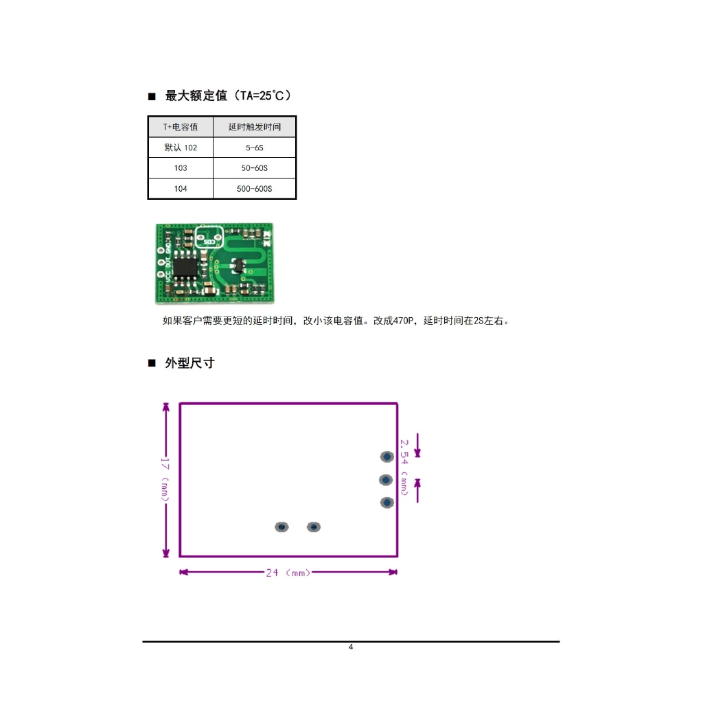
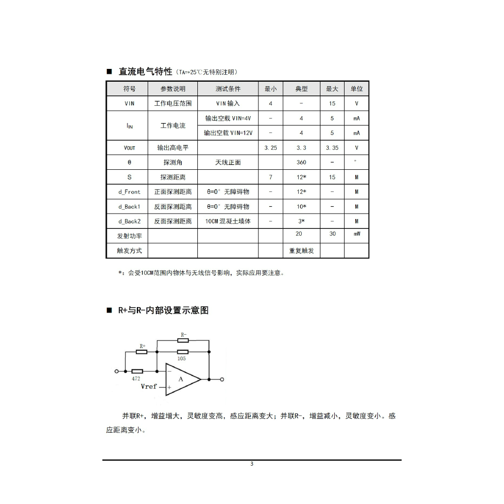
Anyway, according to the datasheet the RCWL-0515 can be used at a supply voltage of 4 to 15 V, works at a frequency of 2.7 GHz and can detect objects at a distance of up to 15 metres. When it detects movement, the “OUT” pin is pulled high for five to six seconds. You can increase this by adding an extra capacitor on the “T+” position. It also has an option to add a light sensor so that it only works in darkness (so it won’t switch on a light during the day), and you can change the sensitivity of the sensor by adding extra resistors on the backside (“G+” and “G-” to increase and decrease it, respectively).
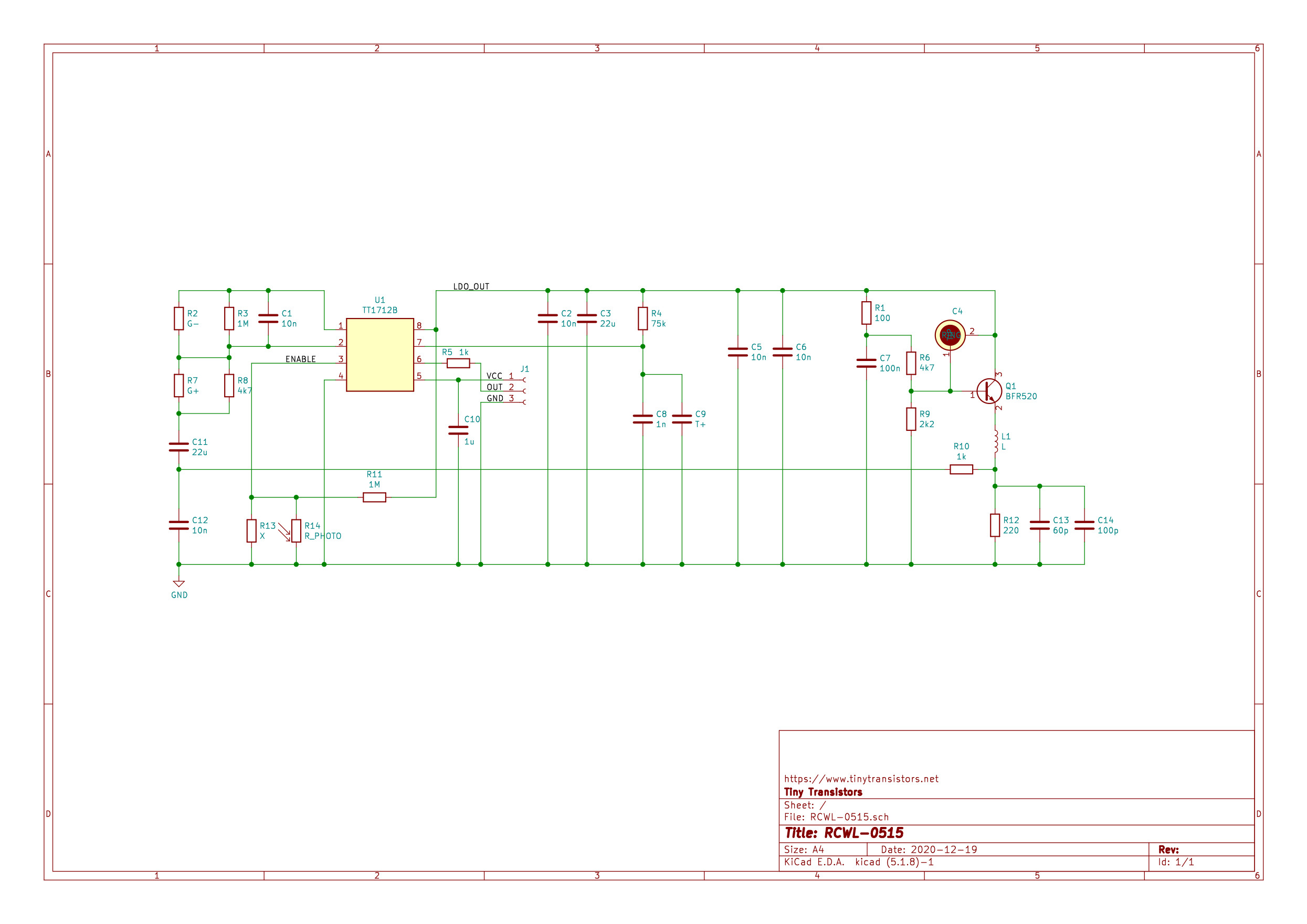
Here is the schematic as I’ve managed to reverse-engineer it. On the right side there’s an oscillator built around the BFR520 transistor. Its oscillation frequency is determined by the inductor L, formed by the S-shaped line on the front of the PCB, and capacitor C4 formed by the circular shapes on the back. R1, R6 and R9 determine the DC operating point, together with R12. The inductor also acts as an antenna, transmitting microwaves perpendicular to the PCB.
When an object moves nearby it changes the impedance seen by the antenna, and therefore the oscillation frequency, which slightly changes the DC bias of the transistor. You could consider this an extremely crude continuous-wave Doppler radar, with the transistor acting as both the transmitter and the receiving mixer (with a zero IF).
The change in DC emitter voltage is AC coupled to U1, which has a comparator with a gain of about 200 as shown on page 3 of the datasheet. If the change passes a certain threshold, the output pin is driven high and a counter is started, clocked by R4/C8/C9. After a certain number of cycles have passed, the output is switched low again.
A photocell can be added to R13/R14 to pull the enable pin low when there is light. Pin 8 of the IC is regulated to 3.3 V by an internal LDO.

This is the main chip, after removing it from the PCB. The only markings are “TT1712B” and a date code “#200404”. It’s a simple plastic SOIC package with, again, no indication of a manufacturer. On the back it says “1712 1117”, which might indicate the production line or a specific batch.
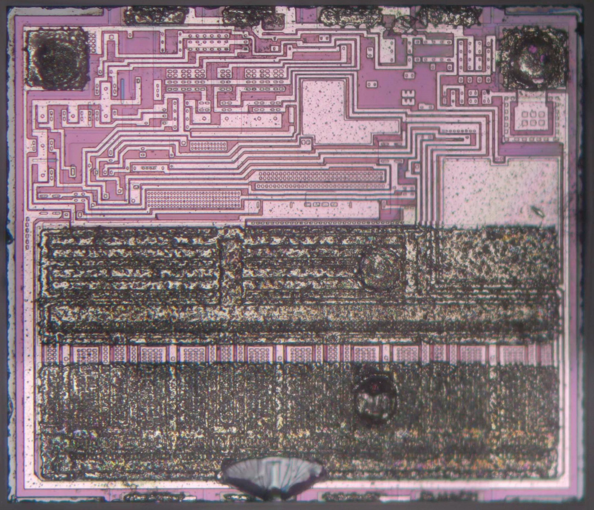
As it turns out after opening the package, I was wrong about those numbers. But first of all, let me share my astonishment that we’re looking at a multi-chip module! There are two separate chips inside the TT1712B’s package, which is something I definitely wasn’t expecting in a device that cannot cost more than a few cents to produce. The “1117” on the back of the package clearly refers to an LM1117 LDO, originally designed by National Semiconductor but nowadays a very popular part in the catalogs of small, unknown IC manufacturers that sell them into cheap consumer goods.
The chip we see above is clearly a voltage regulator: a very large transistor at the bottom with extra thick metal bars to connect it, a simple amplifier circuit above it with two compensation capacitors, and an indication of its output voltage (“33”, meaning 3.3 V). It can easily be changed to any desired voltage simply by moving some of the metal jumpers near the “33” to a different position and changing the label.
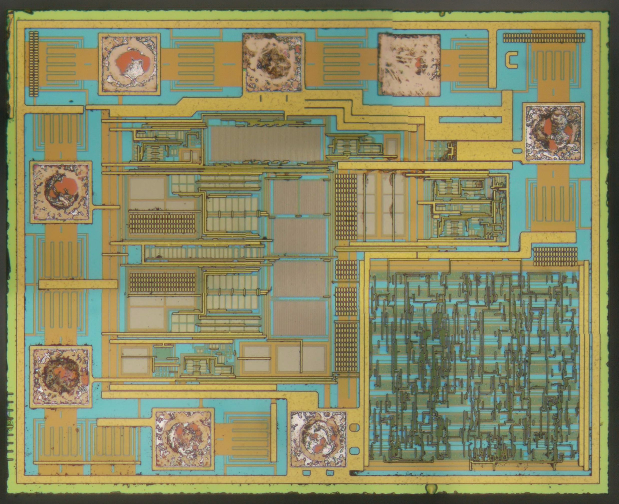
Then there’s the chip that does the rest of the processing; let’s call this the TT1712. There is a block of logic on the bottom-right, lots of analog circuits in the middle and a label “C” at the top-right. Again, as might be expected, no indication of a manufacturer or even the chip’s functionality.
This chip is made in a much more modern process than the 1117: it has two metal layers, much finer features and apparently requires a certain minimum density on each metal layer, hence several locations with dummies (grids of tiny metal blocks).
Working from the datasheet and the PCB schematic, we can figure out what there needs to be on this chip: it should have an amplifier/comparator, a voltage reference (which might just be a resistive divider from the supply voltage), an enable pin, an oscillator (which uses R4/C8/C9 as a timing reference) and a counter that counts the oscillator’s pulses.
It looks like VDD (pin 8, also connected to the LDO’s output) is the pad at the middle of the top row, and GND is the right pad at the bottom row (since it’s connected to the ring around the die). That would mean the left pad at the bottom row is “enable” (pin 3), the two pads on the left are pins 1 and 2 (sensing the signal from the RF section), and the pad on the top-left is pin 7 (RC). The pad on the right would then be the output, while the one on the top-right end might be a test pad (as it looks unused). The two identical (mirrored) sections in the middle of the chip look like an amplfier or comparator. It is likely that one of them is used for the “sense” pins and the other for the oscillator. The counter, with enable functionality and possibly a power-on reset is in the logic block.
I wouldn’t be surprised if this chip is also used in many other products as a generic timer/delay chip. In that case the RCWL-0515 is actually an extremely clever device: sticking together a couple of standard, widely available components and making it into something that performs a useful function that would definitely not be obvious from the components themselves. Whoever designed this thing, good job!
References
This is a very in depth teardown of this module, one I found very interesting. I have been buying a few modules similar to this and I’m mainly interested in the analogue side and the possibilities relating to Ham Radio. At 2.7 Ghz I dont think it could be moved up to 3.2 GHz or down to 2.3 Ghz but it would be fun to have a play. I also have the RCWL-0516 but again, not much use for the ham bands, just a toy to play with. Have you looked at the HFS-DC06? this is yet another microwave module but this time it works at 5.8GHz. What I found interesting was the microwave part is a seperate module with an analogue output to the ‘logic’ board, something I want to dig deeper into.
I forgot to add the link….
https://www.aliexpress.com/item/32786483344.html?spm=a2g0o.order_list.0.0.492b1802r5UinA
Thank you for an interesting tear-down, even if it didn’t answer my questions about how best to use it. 5 years later there is stil very little information about rcwl-0515 but tons about rcwl-0516.
BTW you were ripped off on price. I paid about EUR 0.15 each for three rcwl-0515 and three rcwl-0516. As to origin, My guess woul dbe they are designed for some product that’s made in the millions, and a few thousand leak out into the hobby market.
I bought them because I am sick of meal delivery services that drop our dinner by the front door but don’t ring the bell. They can apparently “see” through walls and glass, so I may be able to make something that doesn’t have to be mounted outside. They were so stupid-cheal it’s worth it to have a play 🙂