I bought this smoke and carbon monoxide detector several years ago, and it’s been doing its job just fine ever since: mostly being silent, screaming when I burn my toast, and beeping every two years or so when its batteries run out. Recently however it began beeping for no reason, and I couldn’t get it to stop other than by removing the batteries. So I bought a new one and decided to tear down the old one.
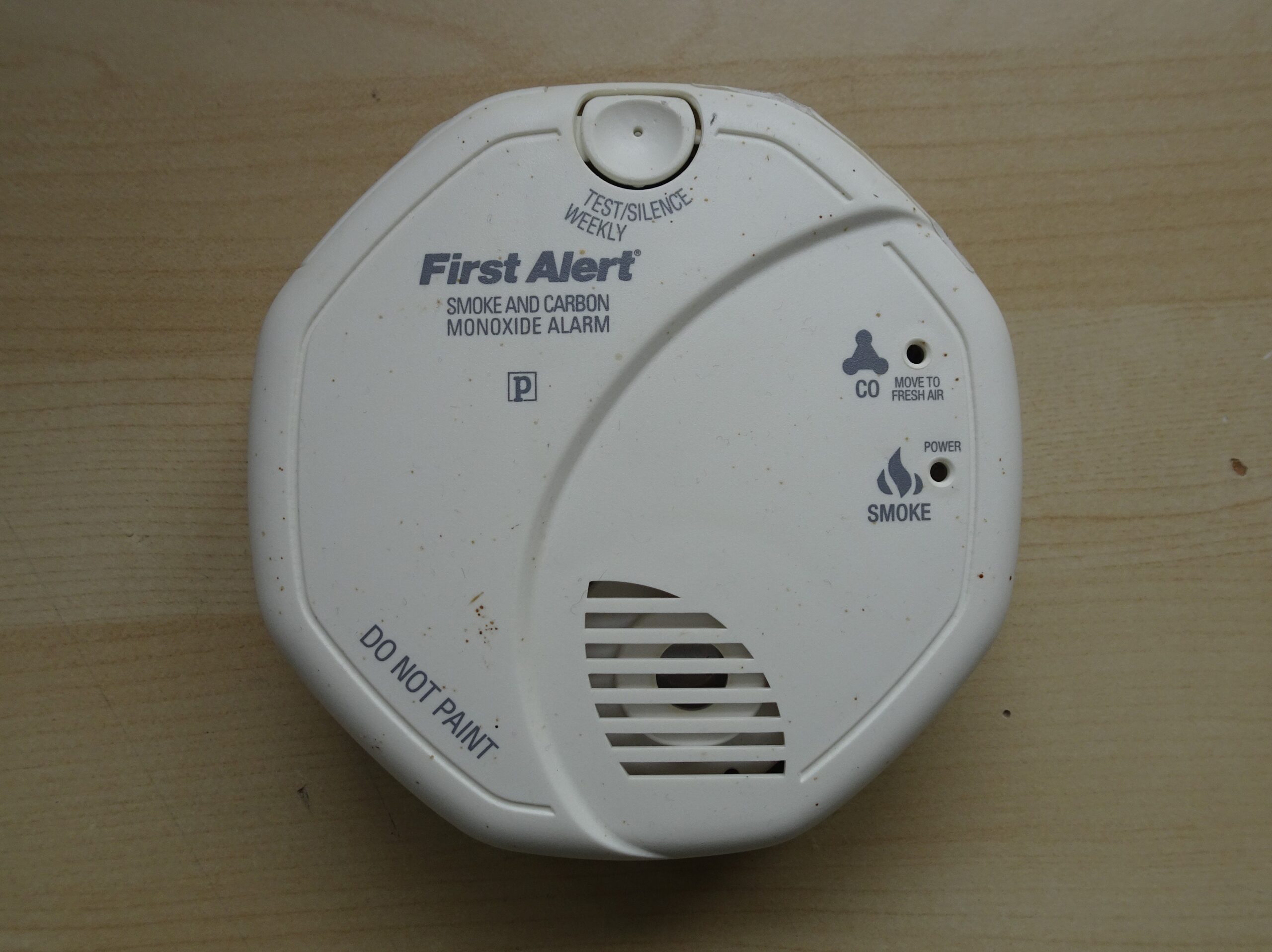
It’s made by First Alert, detects smoke and CO, and has a test button that you’re supposed to use once a week (seriously?). It conveniently runs on two AA batteries. First Alert is an American supplier of fire safety products, currently owned by Resideo Technologies.
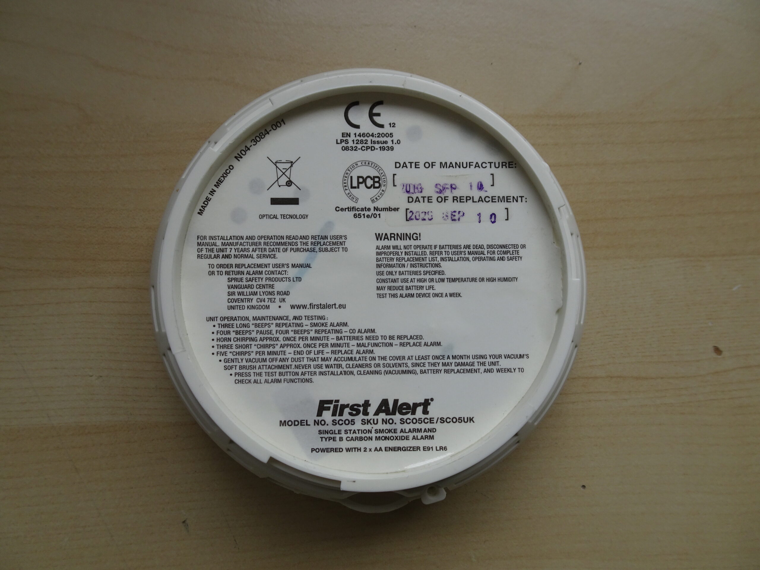
On the back it’s got some usage instructions as well as the date of manufacture and a “use by” date. In both cases the year is not printed very clearly, so I’m not sure if this thing actually reached its supposed lifetime.
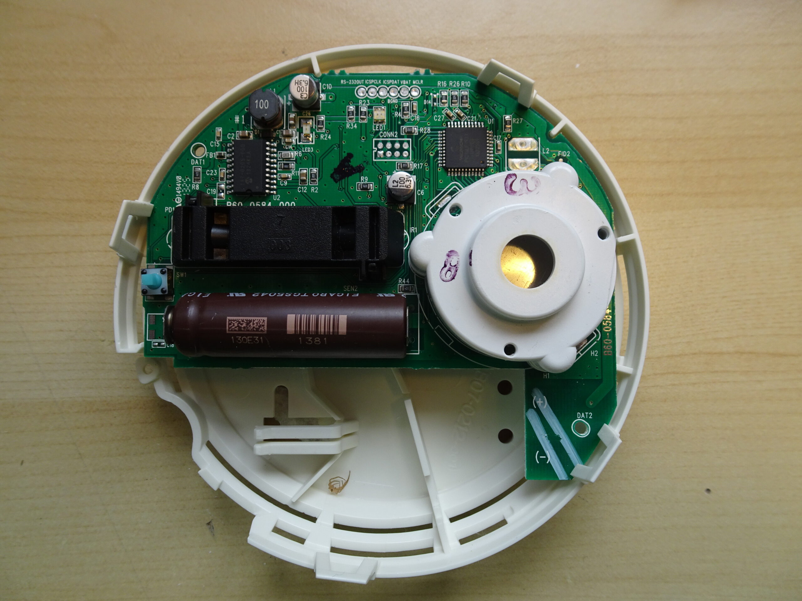
Inside it’s got a single PCB. On the right is a big white buzzer, and on the left are the two sensors.
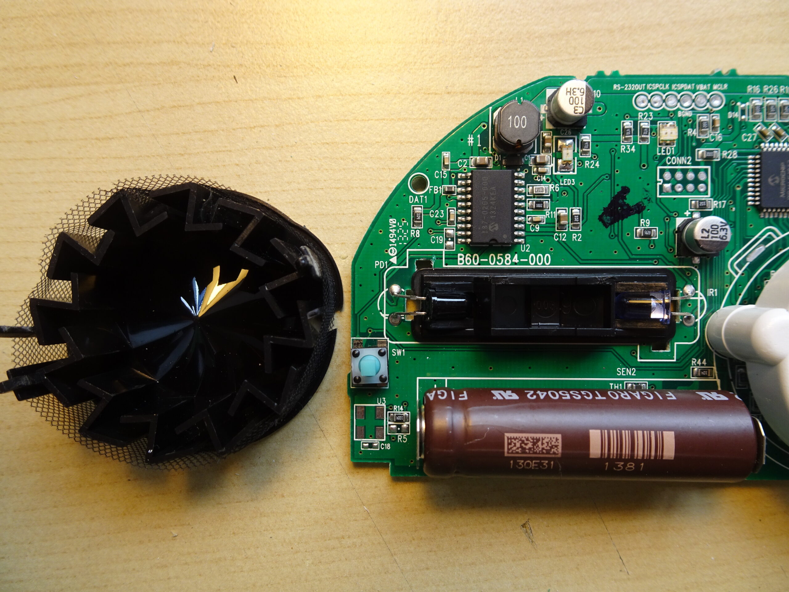
The smoke sensor is of the optical type. An LED shines light into a dark chamber attached to the bottom of the PCB, and if any smoke gets inside, the light will get scattered and partially reflected onto a photodiode. The smoke chamber is made from black plastic and has a clever structure that blocks light from the outside while still allowing air to flow through.
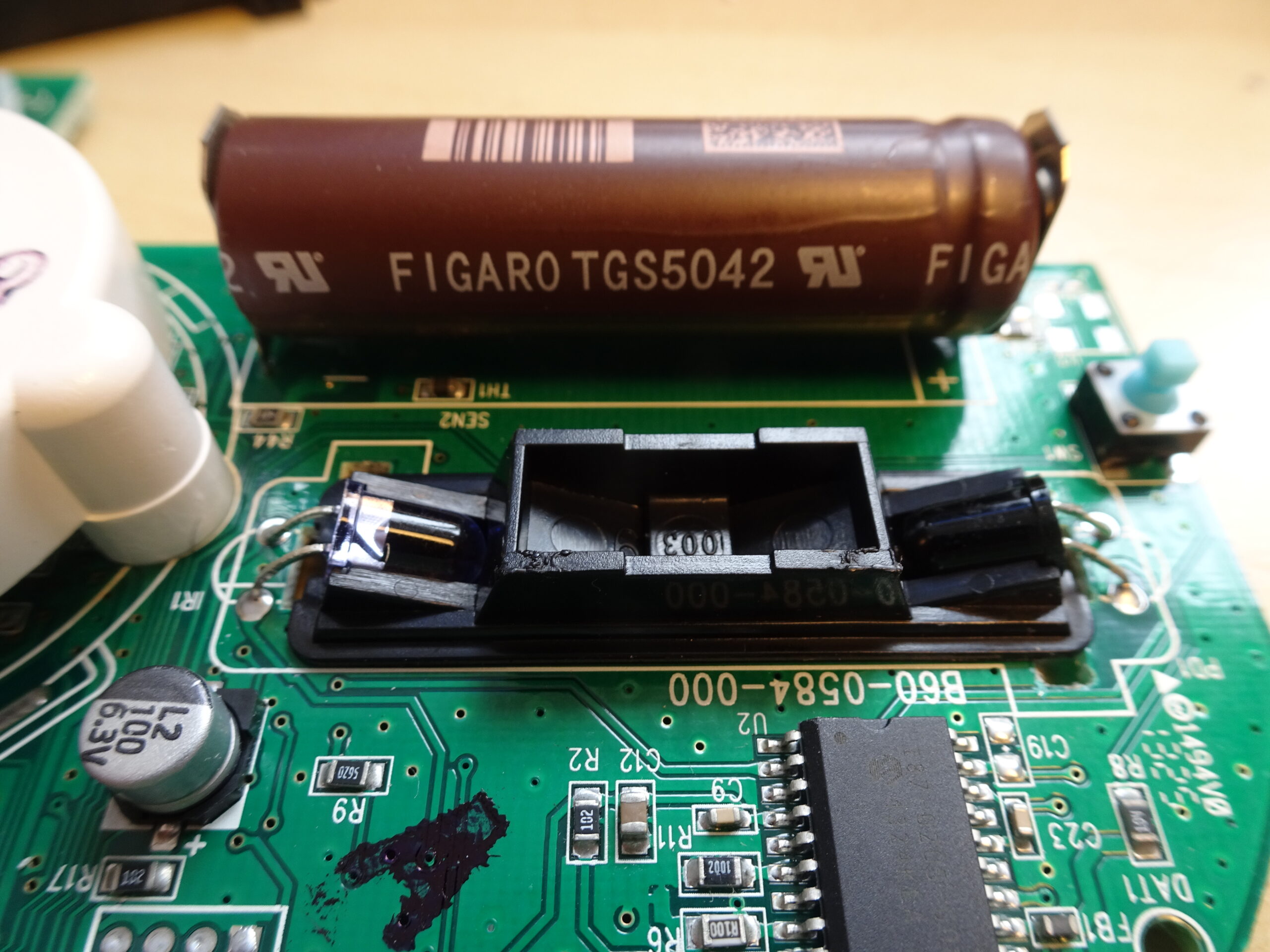
Here’s a more detailed view of the optical sensor: the LED is an infrared type in clear purple plastic (on the left), while the photodiode is housed in an opaque package that’s presumably transparent to IR (on the right). The chip in the foreground drives the LED and reads out the photodiode.
The brown cylinder in the back looks like a battery, but is in fact the carbon monoxide sensor. It’s a TGS5042 made by Figaro and is based on the electrochemical principle: tiny holes on the right side allow air inside, where a platinum electrode causes any CO to react with oxygen to form CO2. The electrons delivered in this process are captured by the electrode and generate a current proportional to the amount of CO in the air. At about 30 euros a piece, the CO sensor is easily the most expensive component in this smoke detector.
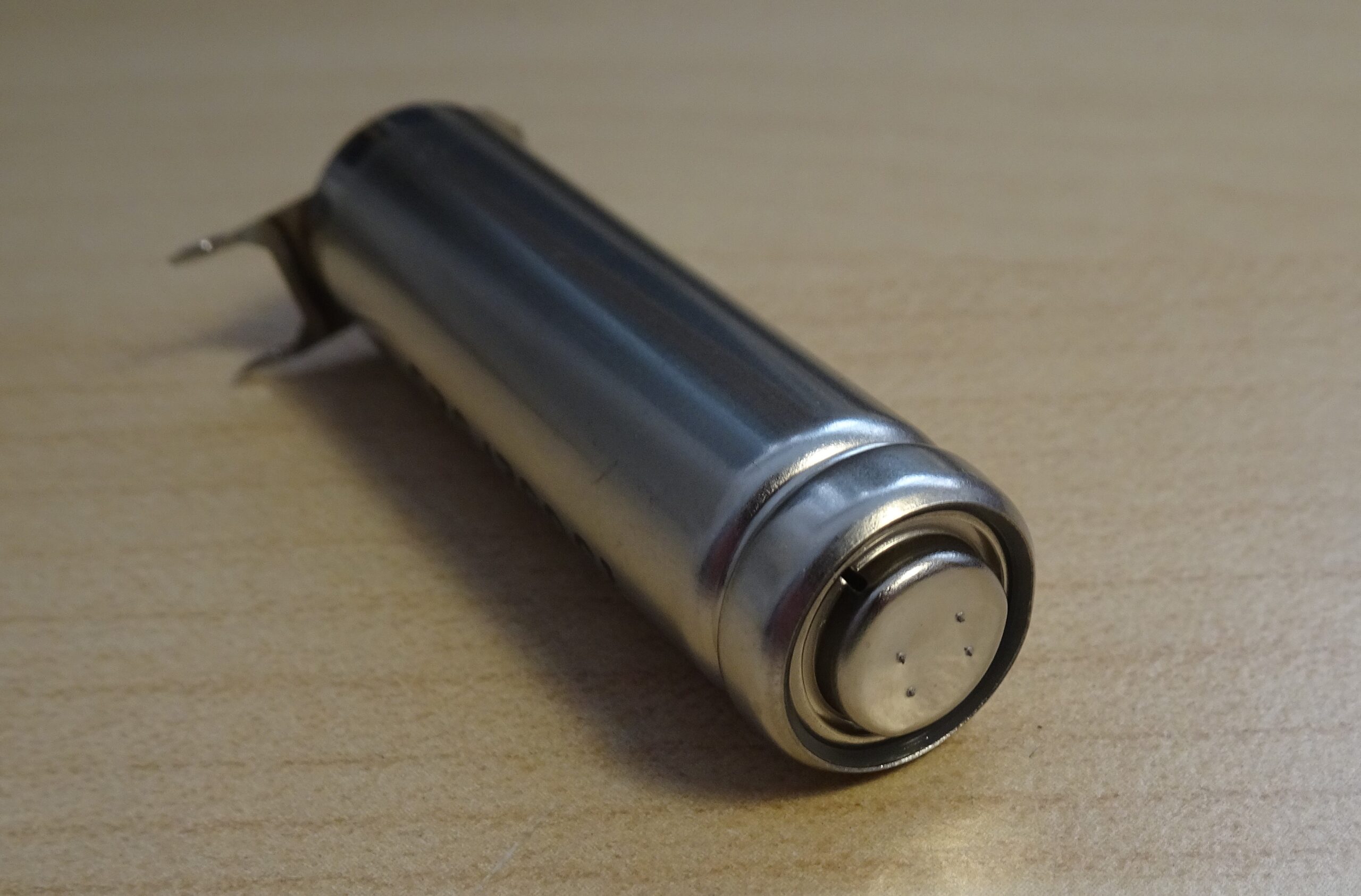
The holes are just about visible on the edge here. The whole assembly is the same basic size as an AA battery; one would assume this sensor is made using the same equipment used to make batteries. In fact some rechargeable NiCd batteries had similar holes to vent any gases that might build up while charging.
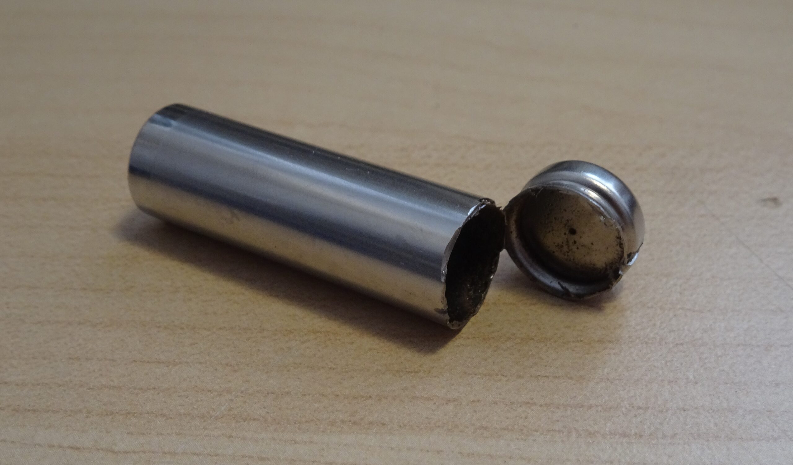
The sensor is mostly a hollow tube filled with a liquid electrolyte, in this case a mixture of potassium hydroxide and potassium carbonate. It’s closed off by a membrane behind the little hole on the right.
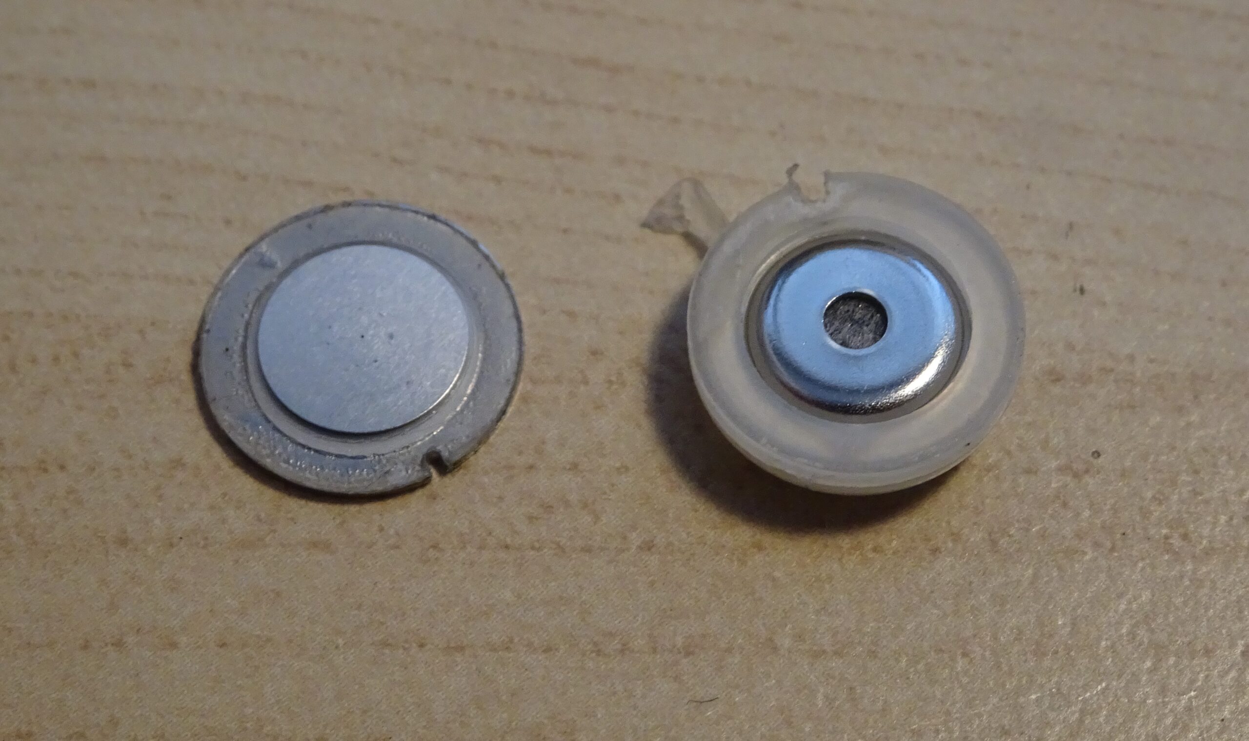
The membrane is covered by a metal plate, which is probably the platinum-coated electrode. The ring on the right contacts the sensor’s external terminal.
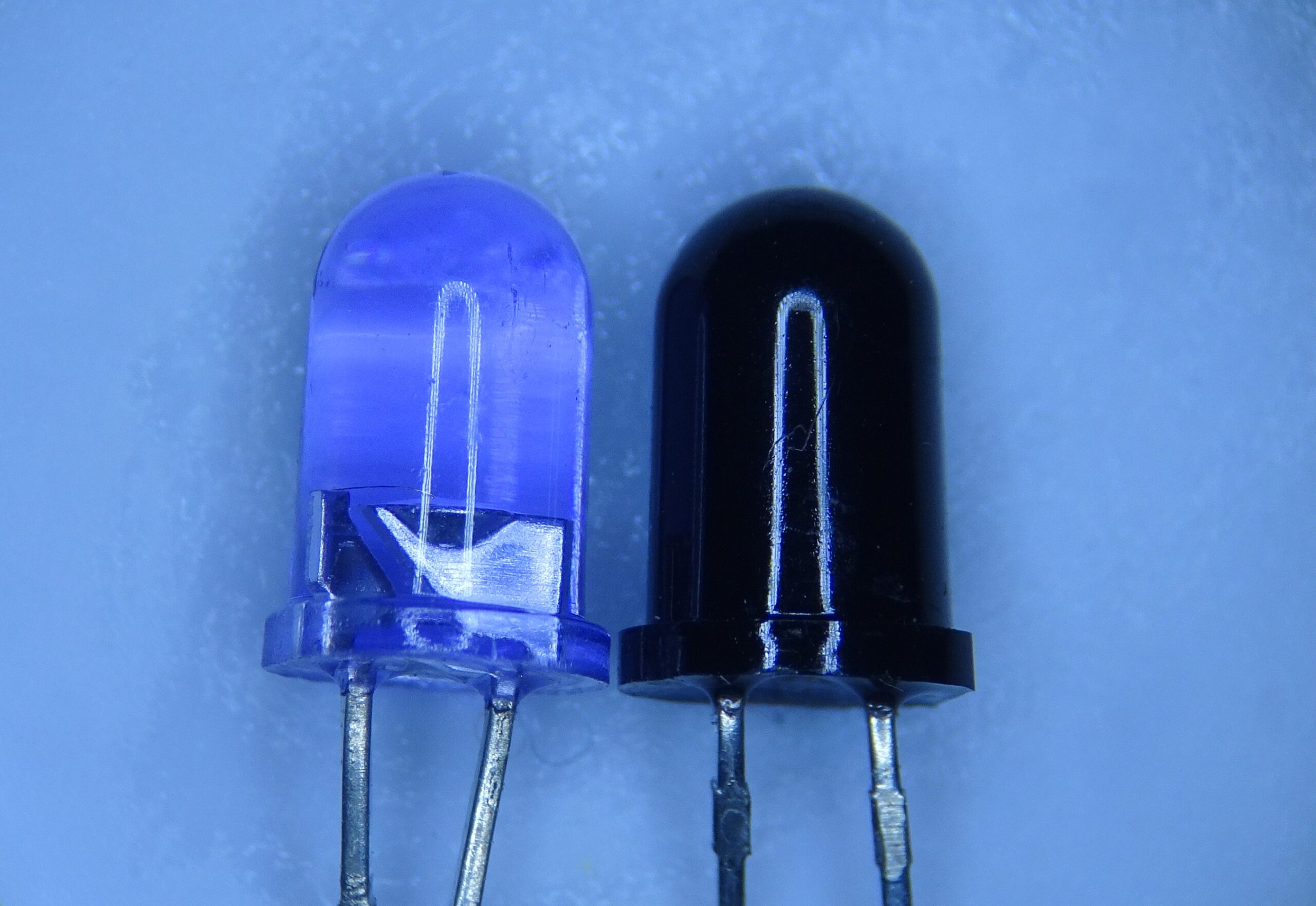
Inside the optical sensor system are these two devices, both housed inside 5 mm LED packages. On the left is the infrared LED, in a transparent purple housing with its cathode on the left and its anode on the right. Note that in most LEDs the cathode is the larger of the two internal pieces, but in this case it’s the smaller bit; the flat part on the side of the package tells you what’s what.
The photodiode is housed in dark plastic, so we can’t see what’s inside. This plastic is designed to be transparent to IR but opaque to other wavelenghts, in order to make the sensor insensitive to anything but IR. Its cathode is on the right, which you can only tell from the flat side of the package being on that side (or from testing with a multimeter).
Note that both of these devices are basically diodes: the only difference is the material that their junctions are made from.
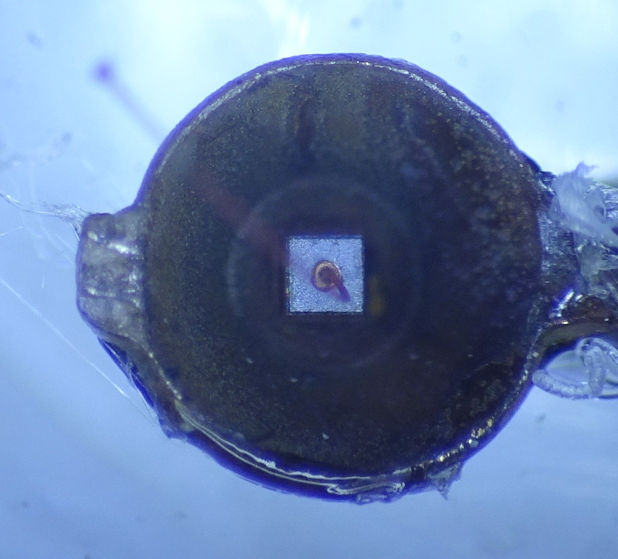
Inside the LED we find this tiny little chip, measuring just 0.3 mm on each side. A single bond wire connects the cathode, which is the chip’s top surface. The bottom is connected to the anode pin, which is shaped like a cup: the light comes out the sides of the chip, and the cup acts as a reflector to bundle the light upwards.
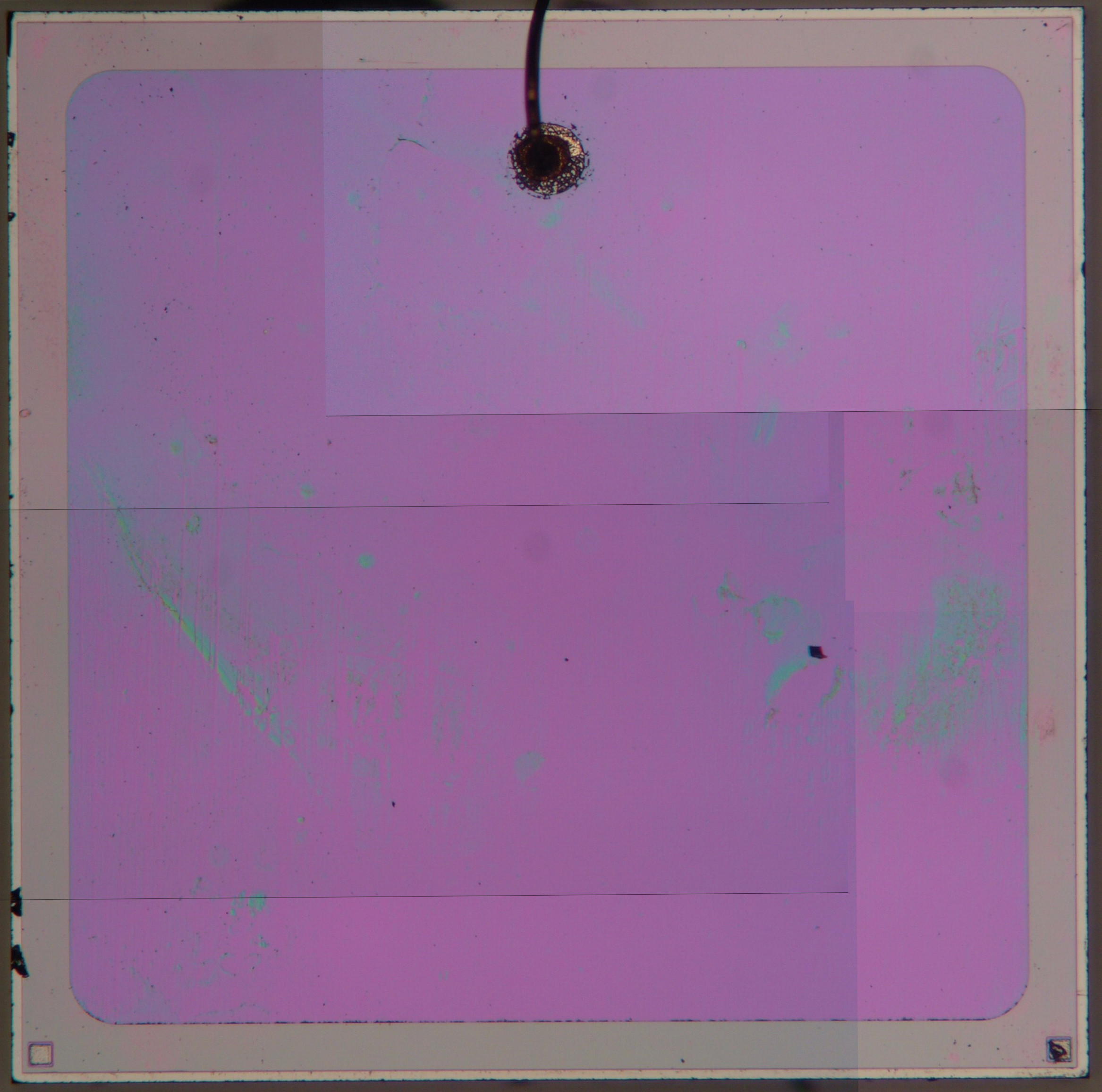
The photodiode, meanwhile, has this rather large chip inside: it’s a 2 mm by 2 mm square. The chip’s design consists of just two layers, one p-type and one n-type, with the top layer contacted through a single gold bond wire. The backside is directly contacted by one of the metal pins. Overall, the package design is similar to that of the LED, although the photodiode doesn’t need a reflector because sensing is done by the top surface rather than the sides of the die.
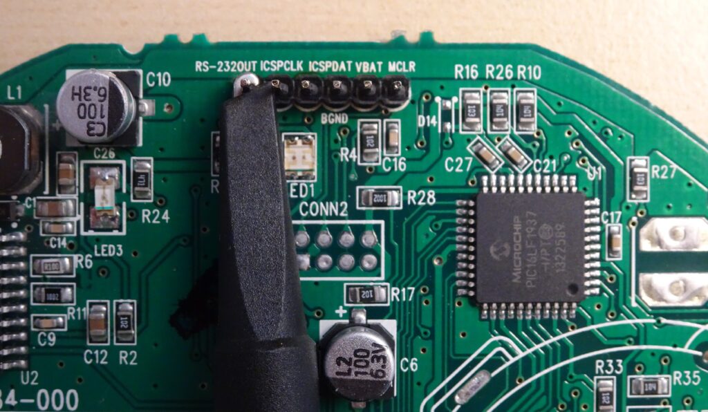
The main microcontroller is a PIC16LF1937 by Microchip, which coordinates all the functions inside the smoke detector. On the edge of the PCB are a few unpopulated connectors, conveniently labelled to tell us what they do. The one on the top has the standard PIC programming pins (MCLR, ICSP data and clock) and also one labelled “RS-232 OUT”. So I attached some pin headers and had a look with my oscilloscope.

It’s an active-high, 9600 bps serial signal. In ASCII, it starts with “{08 3”, so it’s clearly outputting some string with numbers. There’s a burst of signals about once a second; let’s capture the data for a while and see if it makes any sense:
{08 3A 08 0000 C0 0000 0000 ED 16 00 00 00 00 80 00 00 0A77}
{08 2A 08 001E C0 0000 0000 ED 16 00 00 04 00 00 00 01 0A77}
{08 3A 08 002A C0 0000 0000 ED 16 00 00 04 00 80 00 02 0A77}
{08 2A 08 000C C0 0000 0000 ED 16 00 00 04 00 00 00 03 0A77}
{08 3A 08 0000 C0 0000 0000 ED 16 00 00 04 00 80 00 04 0A77}
{08 2A 08 0000 C0 0000 0000 ED 16 00 00 04 00 00 00 05 0A77}
{08 3A 08 0000 C0 0000 0000 ED 16 00 00 04 00 80 00 06 0A77}
{08 2A 08 0000 C0 0000 0000 ED 16 00 00 04 00 00 00 07 0A77}
{08 3A 08 0000 C0 0000 0000 ED 16 00 00 04 00 80 00 08 0A77}
{08 2A 08 0000 C0 0000 0000 ED 16 00 00 04 00 00 00 09 0A77}
{08 3A 08 0000 C0 0000 0000 ED 16 00 00 04 00 80 00 0A 0A77}
{08 2A 08 0000 C0 0000 0000 ED 16 00 00 04 00 00 00 0B 0A77}
{08 3A 08 0000 C0 0000 0000 ED 16 00 00 04 00 80 00 0C 0A77}
{08 2A 08 0000 C0 0000 0000 ED 16 00 00 04 00 00 00 0D 0A77}
{08 3A 08 0000 C0 0000 0000 ED 16 00 00 04 00 80 00 0E 0A77}
{08 2A 08 0000 C0 0000 0000 ED 16 00 00 04 00 00 00 0F 0A77}
{08 3A 08 0000 C0 0000 0000 ED 16 00 00 04 00 80 00 10 0A77}
{08 2A 08 0003 C0 0000 0000 ED 16 00 00 04 00 00 00 11 0A77}
{08 3A 08 0000 C0 0000 0000 ED 16 00 00 04 00 80 00 12 0A77}
{08 2A 08 0000 C0 0000 0000 ED 16 00 00 04 00 00 00 13 0A77}
{08 3A 08 0000 C0 005E 0000 ED 16 01 00 04 01 80 00 14 0A77}
{08 2A 08 0000 C0 0062 0000 ED 16 01 00 04 01 00 00 14 0A77}
{08 3A 08 0000 C0 00AB 0000 ED 16 01 00 04 01 80 00 14 0A77}
{08 2A 08 0000 C0 007B 0000 ED 16 01 00 04 01 00 00 14 0A77}
{08 3A 08 0000 C0 0032 0000 ED 16 01 00 04 01 80 00 14 0A77}
{08 2A 08 0000 C0 0000 0000 ED 16 01 20 04 00 01 0A 14 0A77}
{08 3A 08 0000 C0 0000 0000 ED 16 01 00 04 00 81 09 15 0A77}
{08 2A 08 0000 C0 0000 0000 ED 16 01 00 04 00 01 08 16 0A77}
{08 3A 08 0000 C0 0000 0000 ED 16 01 00 04 00 81 07 17 0A77}
{08 2A 08 0000 C0 0000 0000 ED 16 01 00 04 00 01 06 18 0A77}
{08 3A 08 0000 C0 0000 0000 ED 16 01 00 04 00 81 05 19 0A77}
{08 2A 08 0000 C0 0000 0000 ED 16 01 00 04 00 01 04 1A 0A77}
{08 3A 08 0000 C0 0000 0000 ED 16 01 00 04 00 81 03 1B 0A77}
{08 2A 08 0000 C0 0000 0000 ED 16 01 00 04 00 01 02 1C 0A77}
{08 3A 08 0000 C0 0000 0000 ED 16 01 00 04 00 81 01 1D 0A77}
{08 2A 08 0000 C0 0000 0000 ED 16 01 00 04 00 00 00 1E 0A77}
{08 3A 08 0000 C0 0000 0000 ED 16 01 00 04 00 80 00 1F 0A77}
{08 2A 08 0000 C0 0000 0000 ED 16 01 00 04 00 00 00 20 0A77}
Most of the values are constant, but there’s a few that change over time: for example, the second column toggles between 2A and 3A. Column 4 is mostly zeroes but shows 1E and 2A at the beginning; similarly, column 6 shows five different values about halfway through this log. The second-to-last column is a counter that eventually saturates at FA when you run it long enough.
I’ve no clue what any of these codes mean, but they’re probably status codes that show what the microcontroller is doing at each time instant. Because the smoke detector should work for a long time on a single set of AA batteries, it probably performs all of its functions once a second and stays in sleep mode the rest of the time.
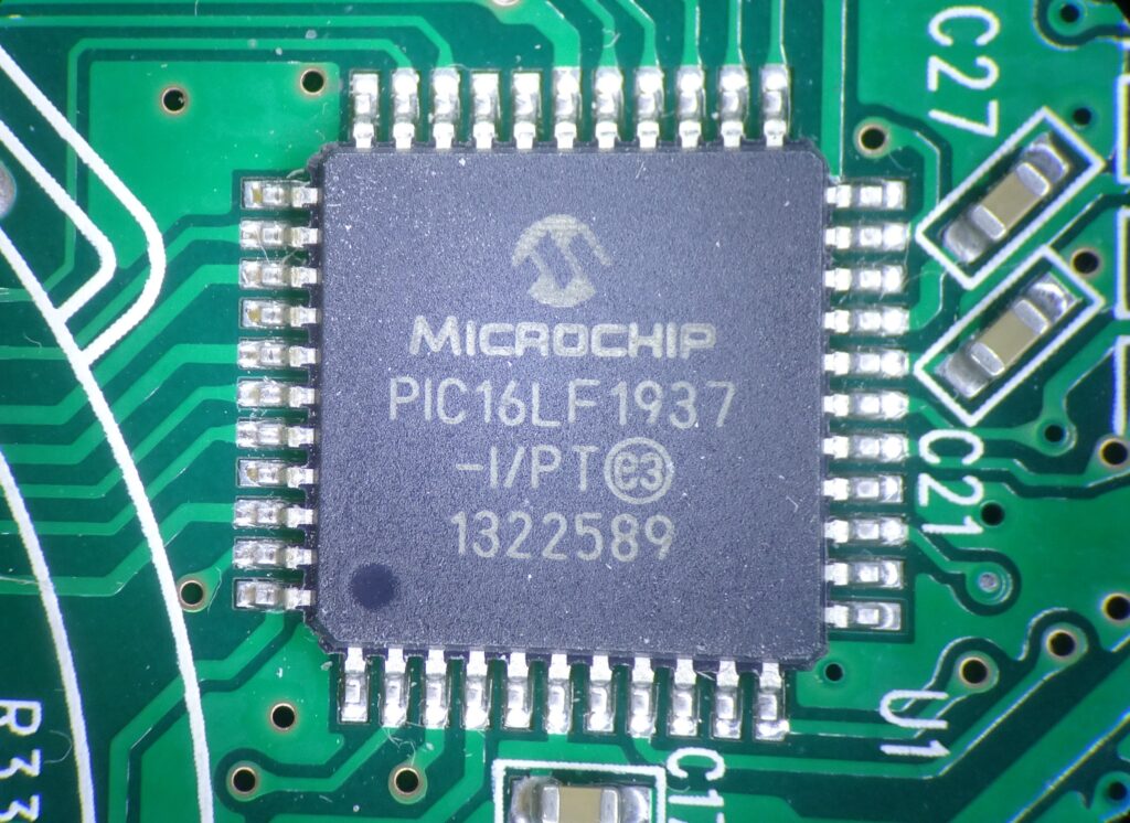
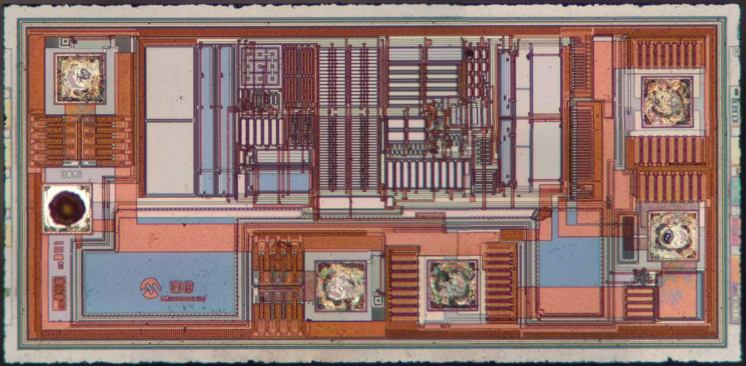
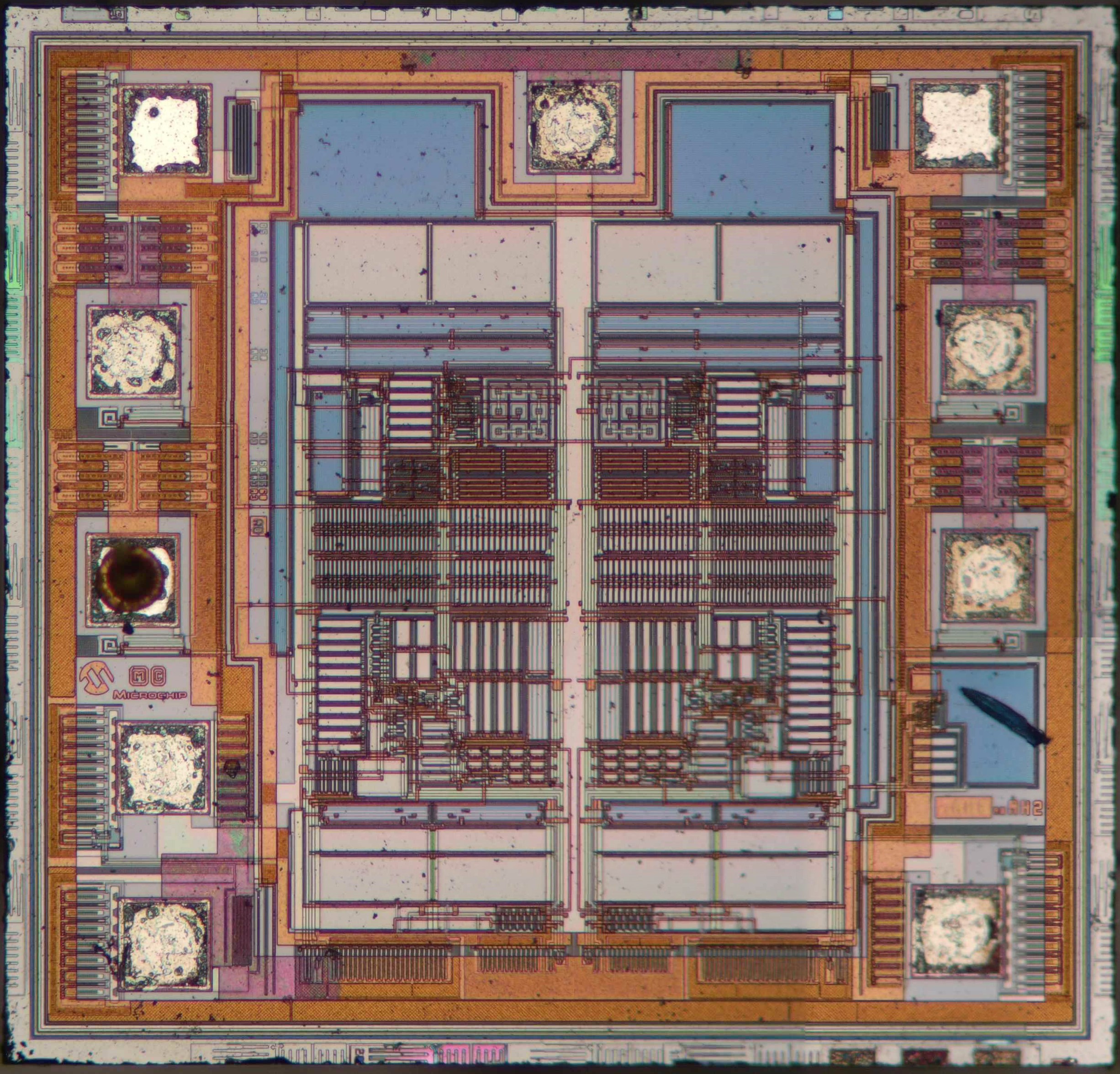
Here’s a closer look at the processor. It’s a PIC16LF1937, which is an 8-bit ultra-low power microcontroller with 14 kB of flash. It works at voltages down to 1.8 V and uses just 60 nA in standby mode.
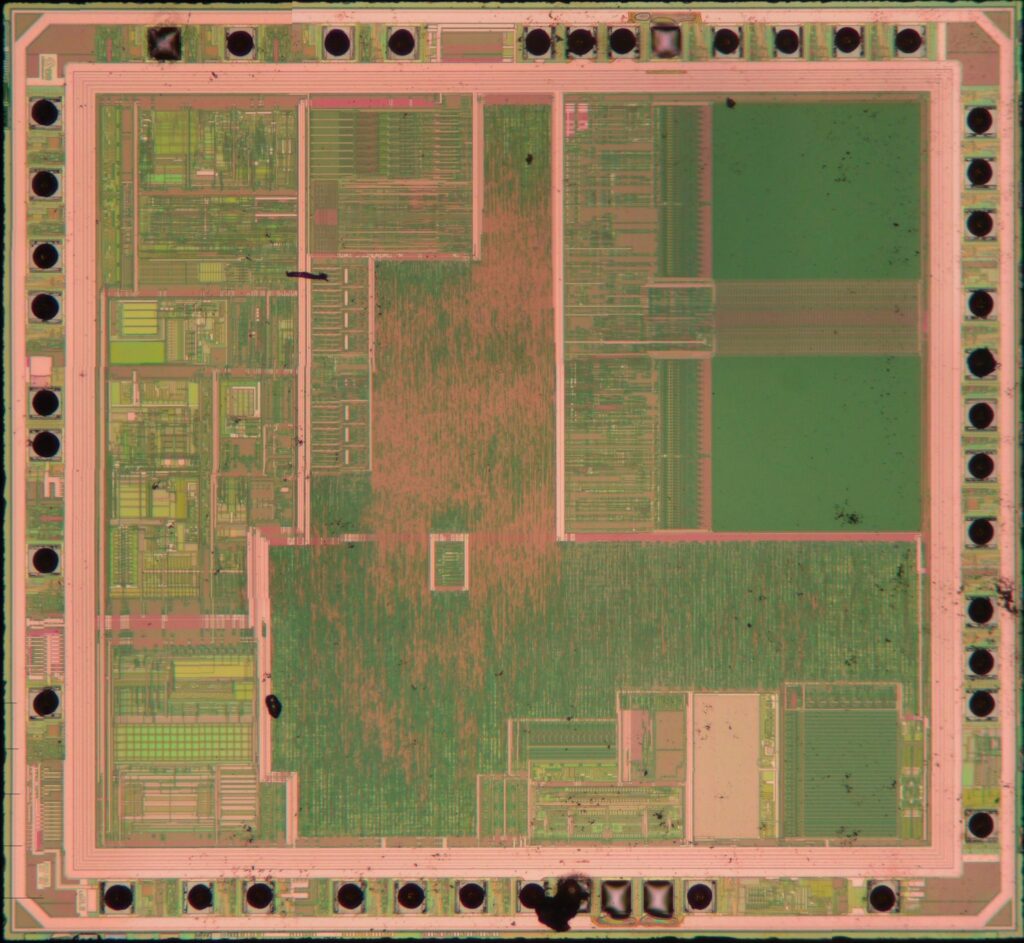
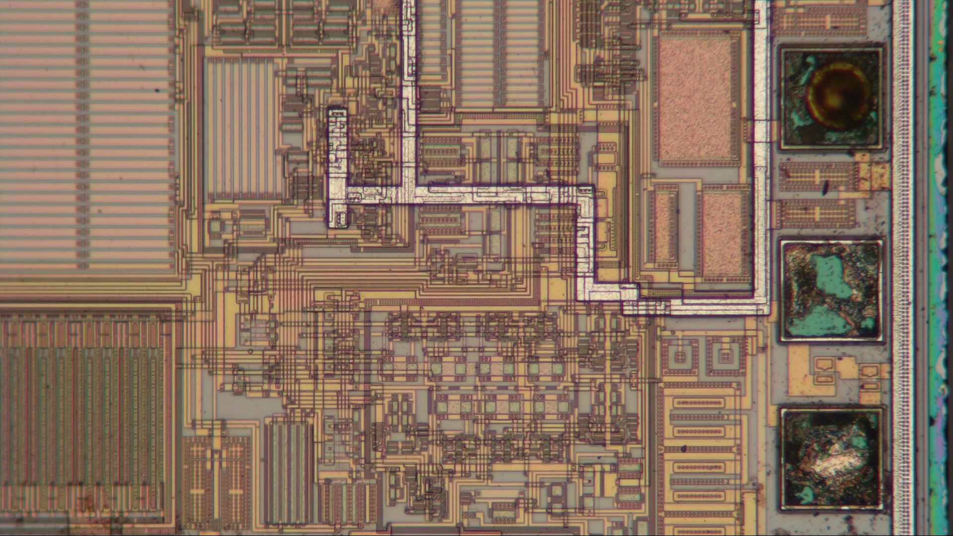
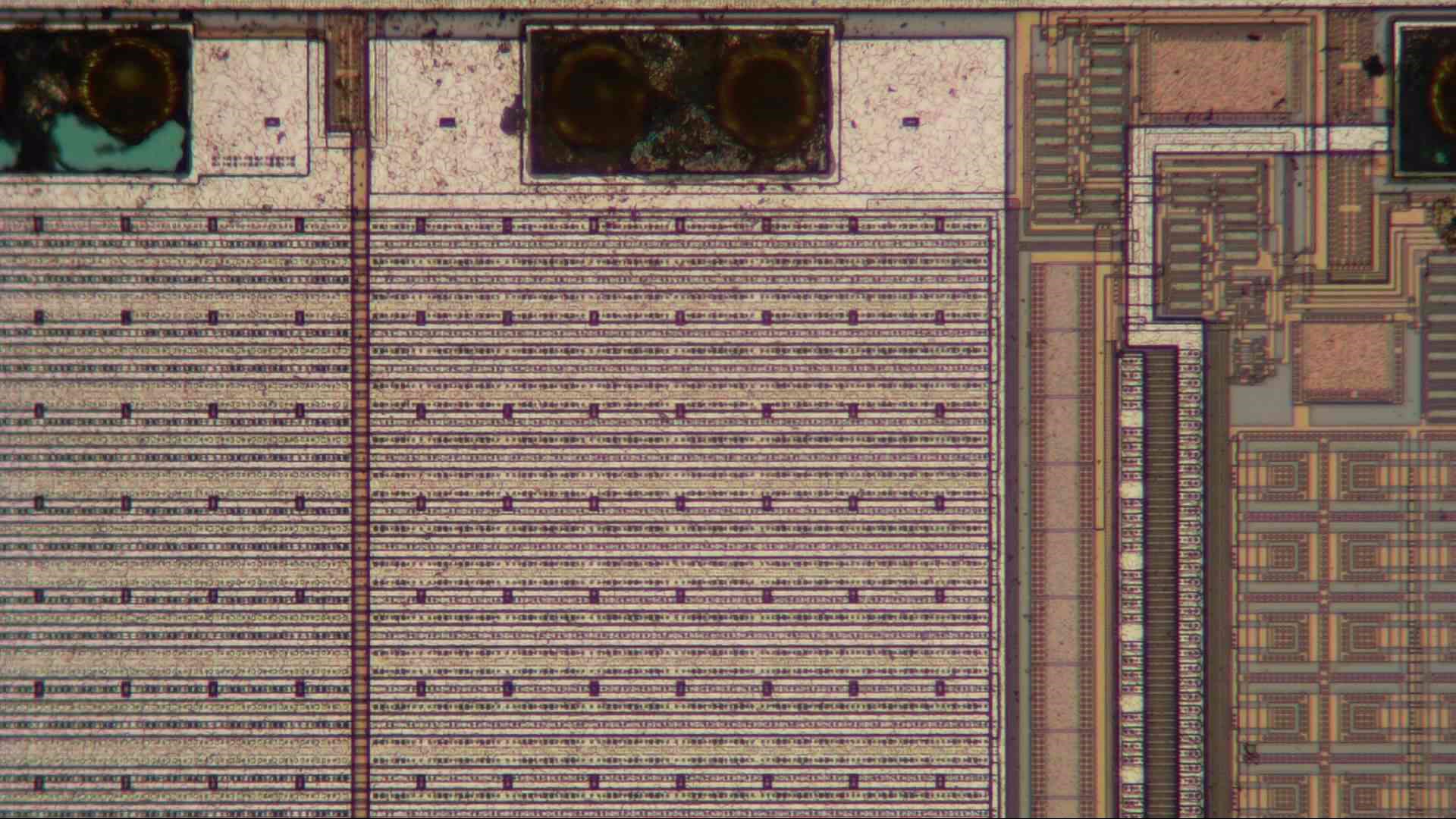
Here’s an overview of the PIC’s internals. Basically, we find analog circuits on the left, digital circuits in the middle and memories on the right. Total chip size is about 2.3 mm by 2.6 mm.
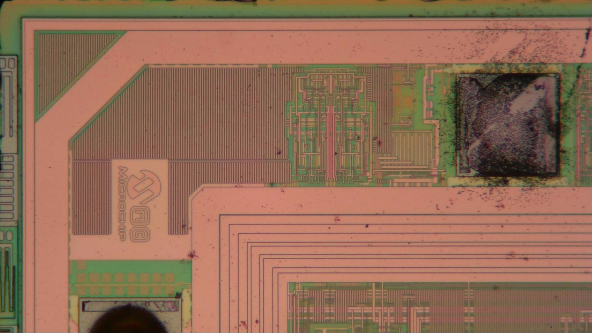
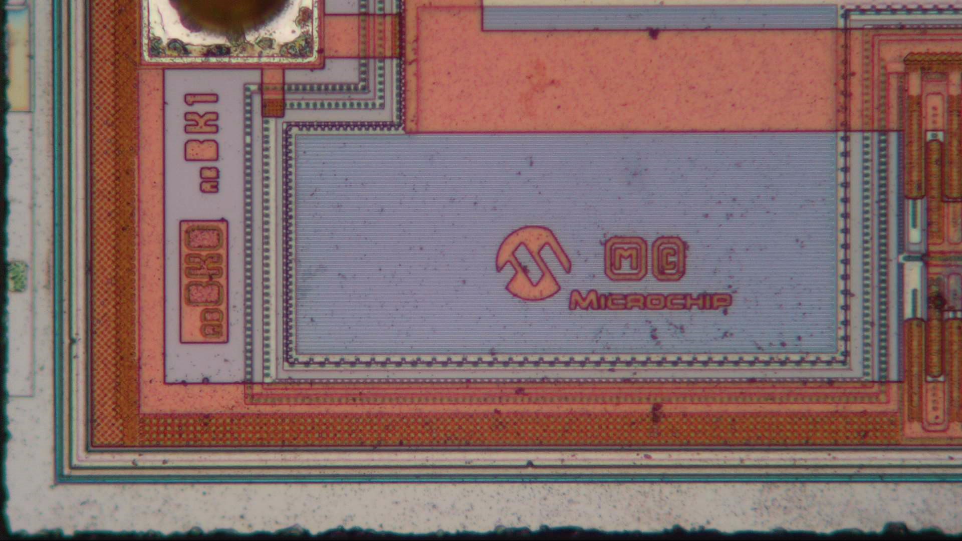
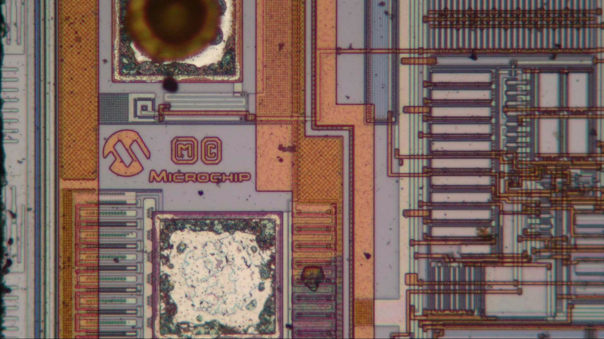
Here we find the Microchip logo, although no copyright date. Note how many lines there are going around this 90 degree corner: those are probably all different power rails. It’s a bit odd that the chip itself only has one set of VDD and VSS pins, rather than separate analog and digital ones.
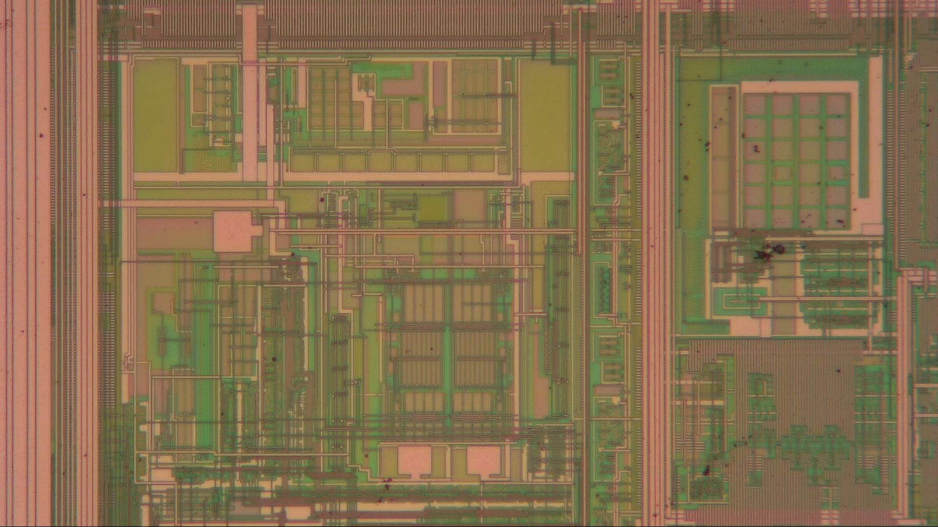
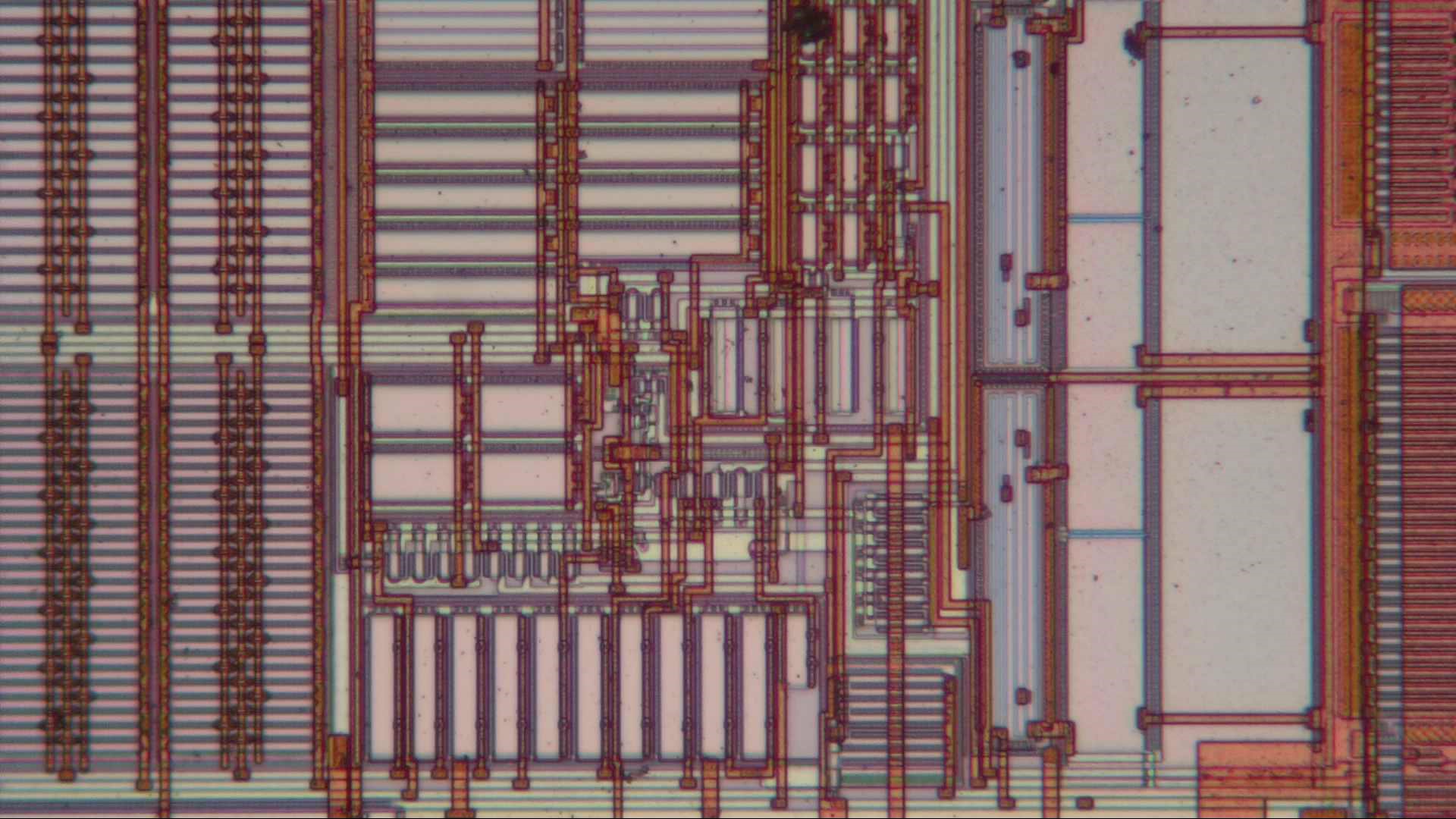
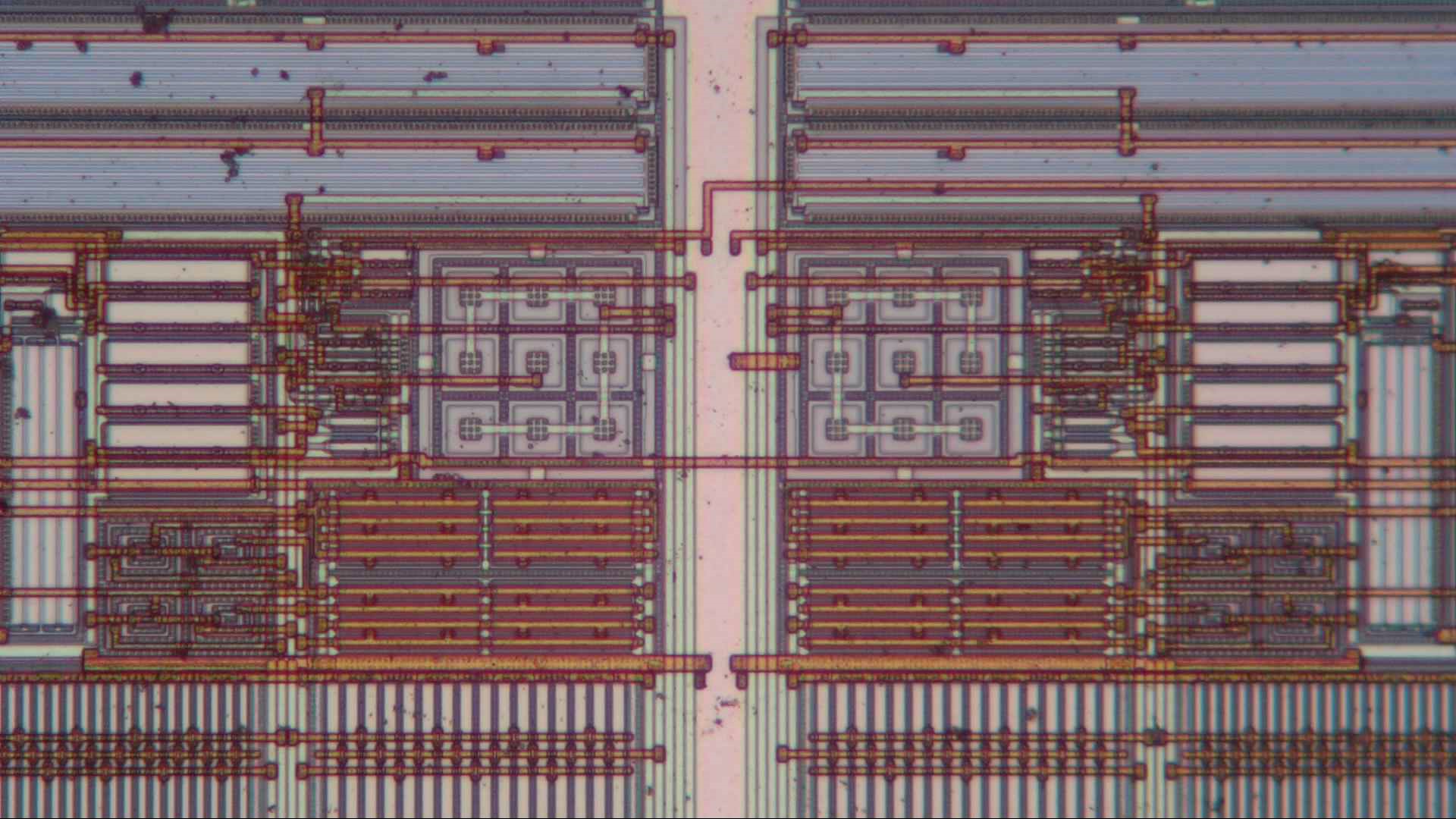
In this close-up of some analog circuitry we find lots of rather large transistors and capacitors.
In the middle of the digital area is this tiny island that looks a bit different.
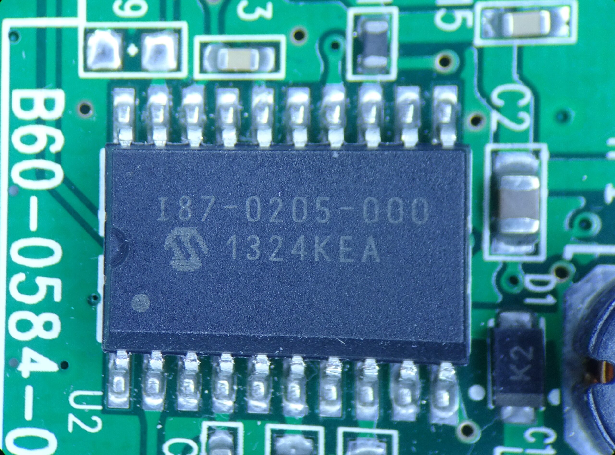
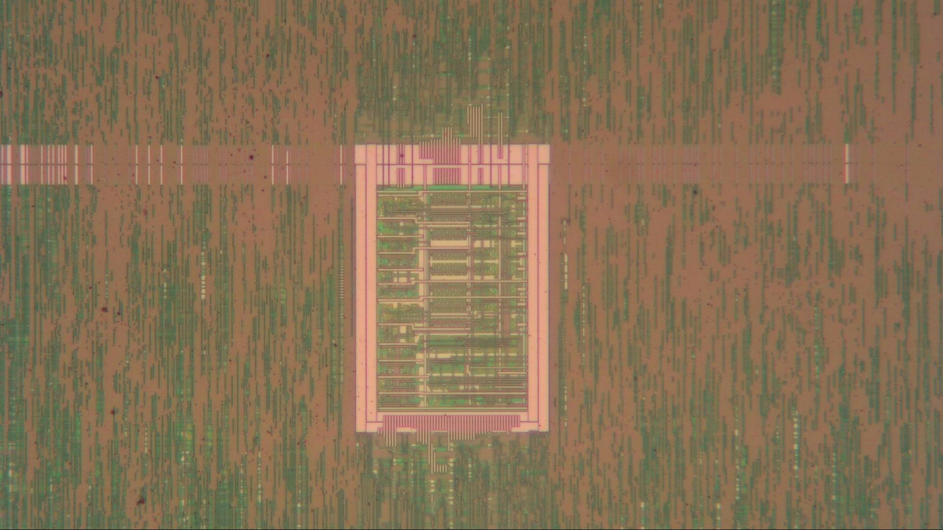
Next to the optical sensor we find this chip labelled “I87-0205-000”. It’s also made by Microchip, but the part number doesn’t return any useful information. The second line is the date code (2013, week 24) and there’s a Microchip logo, but that’s about it. Microchip does manufacture several smoke detector and CO sensor chips, but the part number doesn’t look similar to those. Its package is similar however, so this is most likely a customized version of one of those standard chips, like the RE46C191.
If we open it up we find a rather interesting collection of mostly analog circuitry packed into a 1.9 mm by 1.9 mm square chip. It’s made in a somewhat older process; we can clearly see the individual resistors and transistors. Two large power transistors dominate the top left corner.
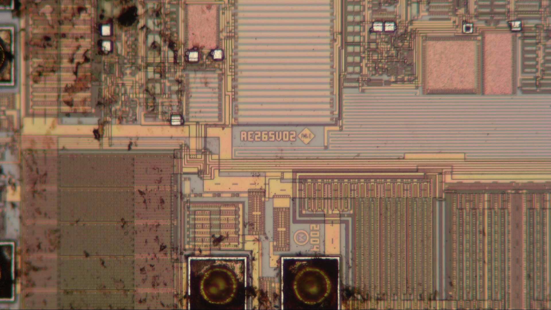
There is a die identifier: RE265V02. Unfortunately, that number doesn’t help much: in fact, it gives exactly zero hits on Google at the time of writing this. There’s a 2004 copyright date as well as a logo that spells out “R&E”. This refers to R&E International, a small fabless semiconductor manufacturer that was acquired by Microchip in 2009. Its name lives on in the RE series smoke detector ASICs that Microchip still supplies. There is no model with “265” in its name though, so we’re left guessing which exact chip we’re looking at here.
We can clearly see the individual transistors here; mostly CMOS devices but with the odd bipolar transistor thrown in as well. Large resistors tell us this is a low-power analog design, while a thick metal layer (the bright line running across the circuits) carries heavy currents.
Here’s a close-up of the output transistors. The RE series chips meant for optical smoke detectors contain a boost converter, which needs one big NMOS transistor. The other one might be an LED driver.
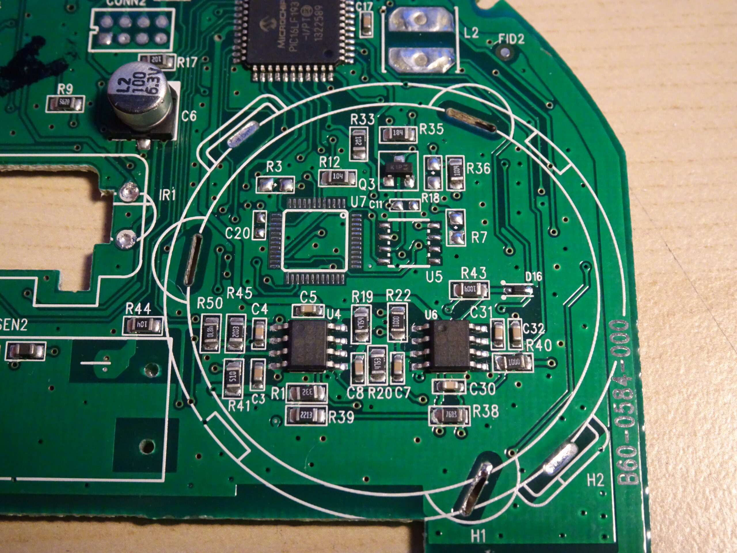
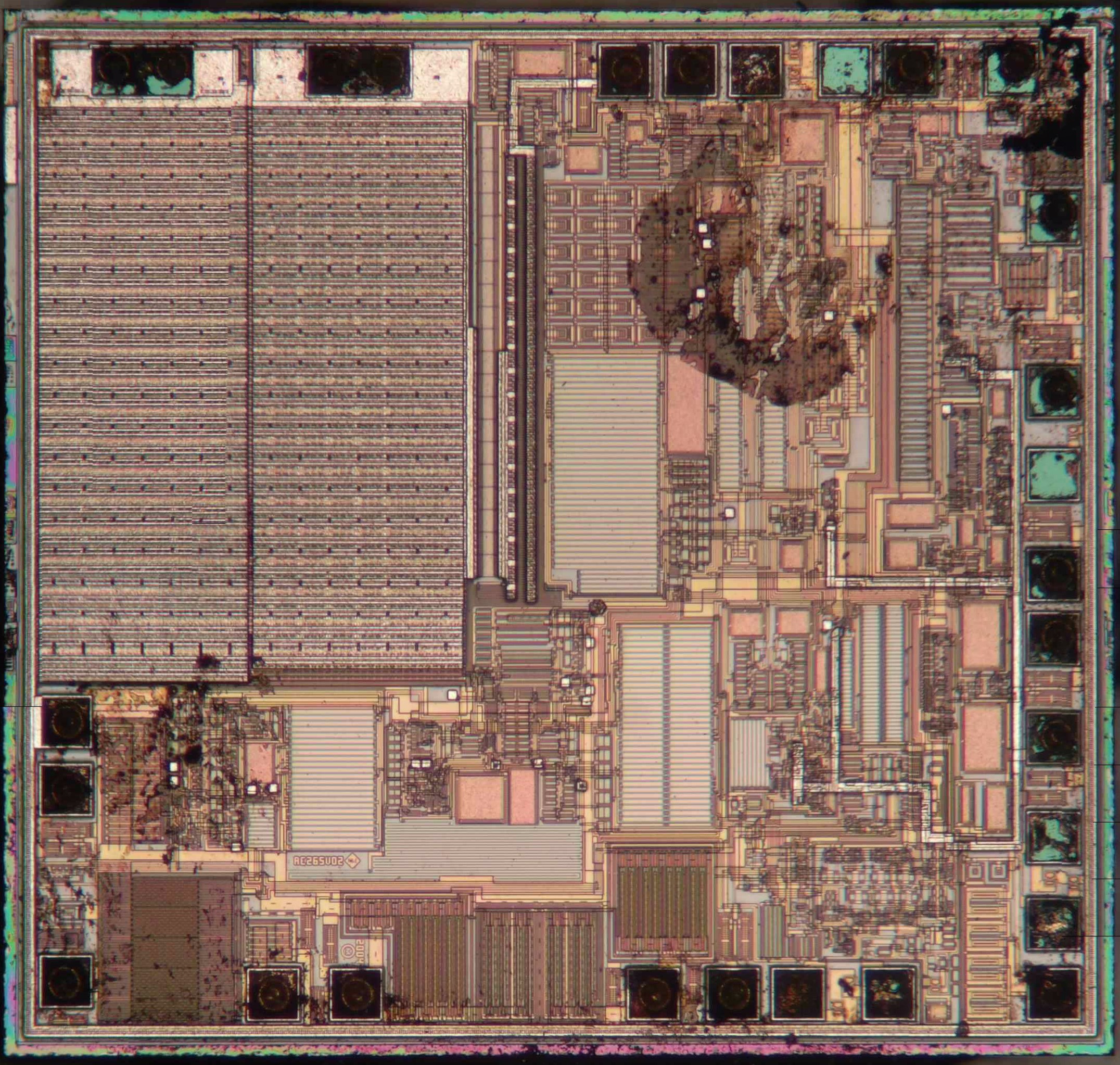
Underneath the buzzer we find this bit of circuitry. The two 8-pin chips are op amps, which amplify the signal coming from the CO sensor. The two unpopulated footprints (U5 and U7) can be used for some different configuration of this board, like a version that can connect to a central alarm system or one that can deliver a voice alarm (both are options available in this range of smoke alarms).
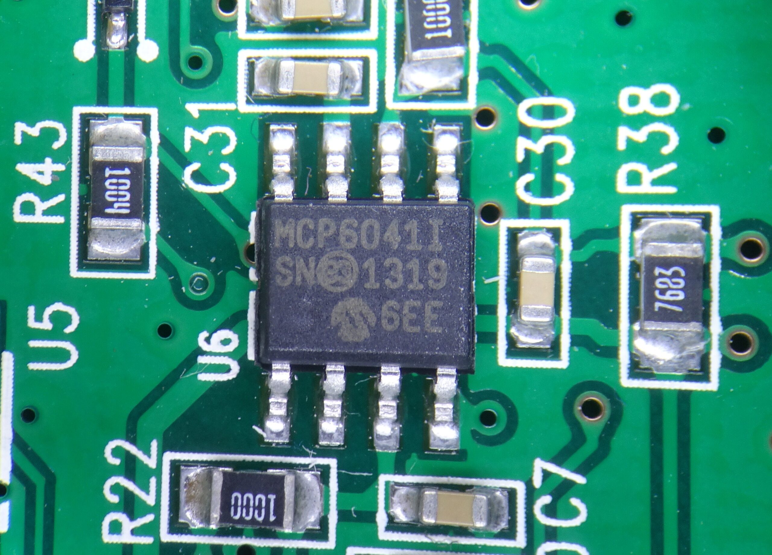
The first of the two op amps is the MCP6041. Again, it’s a Microchip product; in fact, the entire smoke alarm uses only chips made by Microchip. The MCP6041 is an ultra-low power op amp that draws just 600 nA from its supply. Its gain-bandwidth product is only 14 kHz, but that should be plenty for slow-moving signals like CO concentration readings. It’s actually quite similar to TI’s ultra-low power op amps that we looked at recently.
The chip inside is positively tiny: just 0.6 x 1.3 mm2. There are six bondpads, although only five are used in the package. The sixth one is likely only used during testing. We see several arrays of matched transistors in the middle, as well as several large blue capacitors and resistors.
The Microchip logo is placed on top of a large resistor. Again, large-value resistors are an essential part of ultra-low power chips, but inconvenient from a manufacturing standpoint because they tend to take up lots of area.
At the heart of the chip are lots of matched arrays of CMOS transistors. The horizontal and vertical bars are groups of identical transistors; by drawing them right next to each other designers ensure that their performance is as uniform as possible, which helps to achieve a low input offset voltage.
Finally, the last chip on this board is an MCP6042, which is a dual version of the MCP6041. Like all other chips on this board, this one has a 2013 date code.
At 1.0 x 1.0 mm2 it’s about twice as big as its single-amp sibling, but otherwise looks similar. The circuits in the middle are almost exact mirror images of each other. The pad ring is slightly asymmetric though; note that there are ten bondpads, while the package only has eight pins. This suggests that each amplifier has its own test pad.
There was enough empty space near the pads to place the Microchip logo.
Here in the middle we see just how symmetrical the chip is; it looks like only one small wire travels between the left and right amplifer. It’s a bit odd that the two amplifiers don’t even share a common bias current generator; usually designers can save a bit of power by only having this circuit once. Here there’s clearly two separate bandgap references (the 9×9 square arrays), so apparently Microchip’s designers didn’t think it worth the effort.
Hi,
Thanks for the in-depth explanation. I spent a few years repairing radar a long time ago, so I actually understood about 5{684d88caeaea11df97b4707db4900e0b3a8d2f739f69707463db5f51e5389d4d}.
I have 4 SC9120B devices, all about 2 years old. One of them chirps, once every ten minutes, but only at night, for some reason. Since that unit is somewhat redundant, (it’s just outside a bedroom door, and another one is just inside the door) I removed the AC feed and the battery. The chirping didn’t stop. Is it possible that some residual power is held in capacitive devices? Or might there be some on-board micro battery powering the chirp?
Thanks again, Tim
Great review,
Would you know where on the board we can trigger the CO event? Initially I thought it was one of the unpopulated connectors, but as I read through here there would be definetely somewhere else.
Hi Rodrigo! I haven’t dissected the PCB any further than what I’ve shown here, so I don’t know if it has any way to trigger a CO event. In any case you could just apply a small current to the CO sensor and thereby override the sensor’s output. But be sure to check the sensor’s datasheet for the proper voltage and current levels to avoid damaging it.