The DS18B20 is a digital temperature sensor that communicates through the One-Wire protocol. Like the DS2401 that we looked at earlier, it is housed in a three-pin TO92 package and can be read out using just one pin (plus ground). It’s made and sold by Maxim Integrated, although still labelled “DALLAS” on the package. Introduced in 1999, the DS18B20 was the successor to the DS1820 and provided a higher resolution (up to twelve bits, instead of the DS1820’s nine).
This part has become wildly popular over the past few years, because it is reasonably cheap, quite accurate, and very easy to use with microcontrollers. It is widely available online, but its popularity has, unfortunately, also given rise to an industry of fake DS18B20s. Although they usually work, there is no guarantee that they meet the specs listed in Maxim’s datasheet.
These fake chips are made by small semiconductor companies that have designed a drop-in replacement for the Maxim part, copying the exact functionality. There’s nothing wrong with second-sourcing a part like that (it’s how many semiconductor companies started in the first place), but marking them with the Dallas brand and selling them as if they’re genuine Maxim parts is of course illegal. Most likely it’s not the manufacturers that apply the fake label, but shady companies that buy large stacks of second-source chips, re-label them and sell them as if they’re the real thing.

I bought a few DS18B20 chips online. The one on the left is a genuine one, bought from a reputable distributor for €3.97. The one on the right I bought from a discount shop, where they cost just €1.08 each. That huge price difference already suggests something’s fishy. Both say “Dallas 18B20” followed by date and lot codes (2020, week 33 on the left, and 2019, week 21 on the right). In both cases the text is laser-etched into the surface; it used to be easy to spot fakes because they generally had their text printed on in ink, which sometimes was very easy to rub off. In this case, the only way to tell real from fake is the thickness of the letters, but once the counterfeiters get their hands on a better laser-etching machine that difference might be gone too.
Both parts appear to work perfectly fine. Like all One-Wire devices they contain a unique serial number that can be used to identify each individual chip. The two genuine parts I bought had serial numbers 00000CF520F2 and 00000CF5576E. Two of the fakes were 012037C588C7 and 012037B50E7C. Maxim does actually offer customized serial numbers for some One-Wire devices like the DS2401, in which the twelve most significant bits will be used as a customer code, although they don’t mention such a service for the 18B20. Whether the counterfeiters actually reserved a block of numbers from Maxim or simply chose high serial numbers to avoid clashing with Maxim’s is unknown.
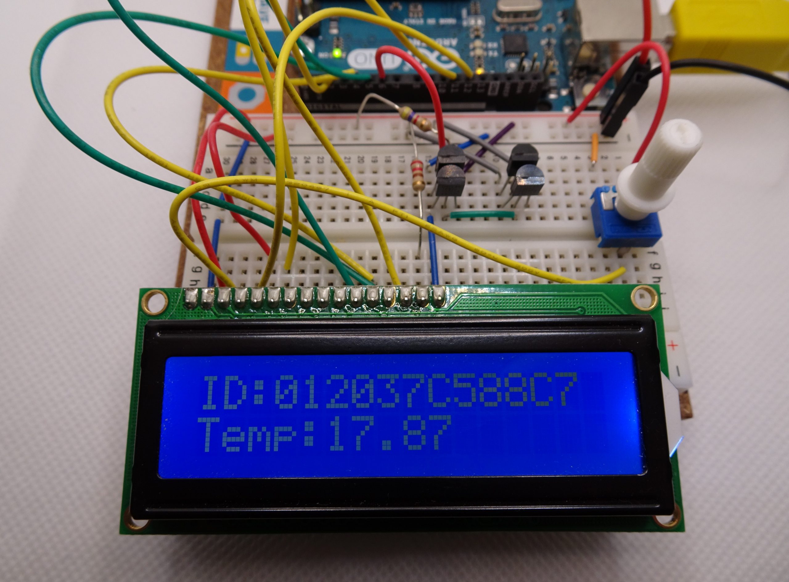
Here is my Arduino test setup to read out the DS18B20s. The One-Wire bus makes it very easy to use multiple devices at the same time: you just connect them all in parallel! Your microcontroller can then scan the bus, find all serial numbers and address the sensors individually.
To test the accuracy of these sensors I placed this whole setup outside, where it was around five degrees C, and recorded the sensors’ output for five-and-a-half hours. I plotted the results below.

As you can see, all parts track the local temperature very well. Even the funny spike around 18:00 is reproduced on all four devices. The noise level on all sensors is no more than one LSB (0.06 degrees). The only real difference between the four chips is the exact value of the temperature reported. Without a calibrated thermometer it’s impossible to tell which value is correct, but it is interesting to see that the two Maxim devices (blue and orange) differ by less than 0.2 degrees, while the two fakes disagree by about 0.5 degrees.
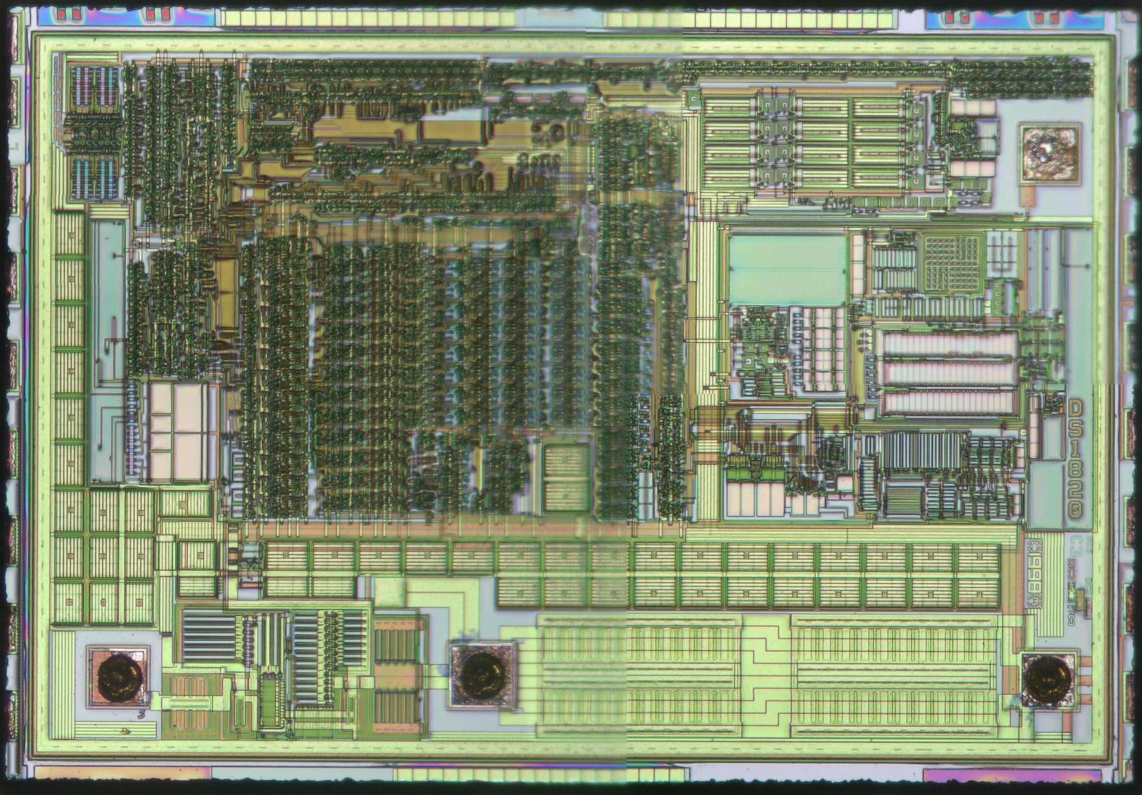
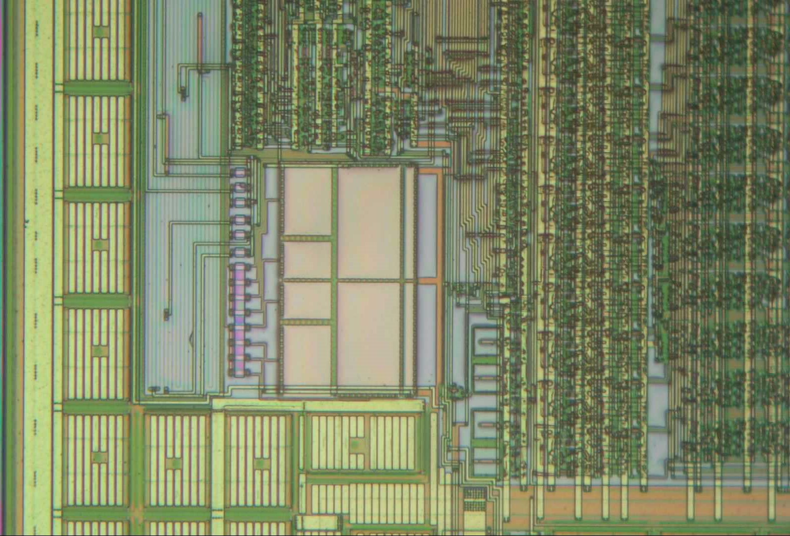
Inside the real DS18B20 we find a nice, compact, mixed-signal layout. The large output transistor is between the two pads at the lower right. At the middle-right side of the die is the temperature sensor core. Digital circuits take up about a third of the area, and we also see the capacitor banks (that supply the chip with power when the data line is low) on the left edge and from left to right along the lower half of the chip. Three bytes of EEPROM are stored in the middle of the die.
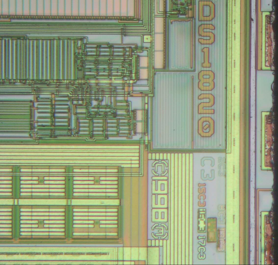
Interestingly, the die is not marked “DS18B20” but “DS1820” which is its predecessor. Perhaps Dallas decided to simply make this as an update to the earlier part, since they are compatible (you can plug in an 18B20 anywhere you use an 1820). We see a 1998 copyright date and a set of layer identifiers.
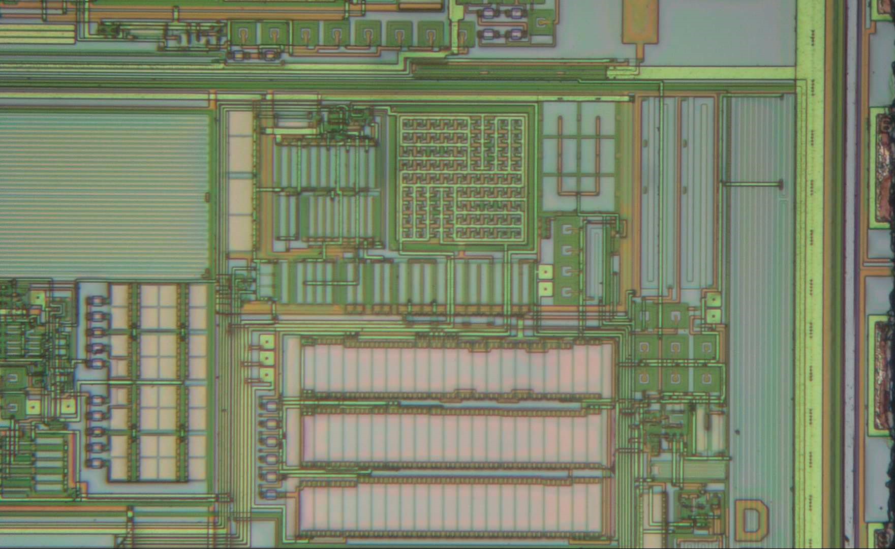
The core of the temperature sensor is in here. Most likely the large square structure is an array of bipolar transistors that generate a temperature-dependent voltage. Below it is an array of resistors (pink) that can be trimmed using laser fuses (the six small squares to its left). Together with a bunch of transistors it forms an amplifier to make a suitable signal for the analog-to-digital converter (on the left side).
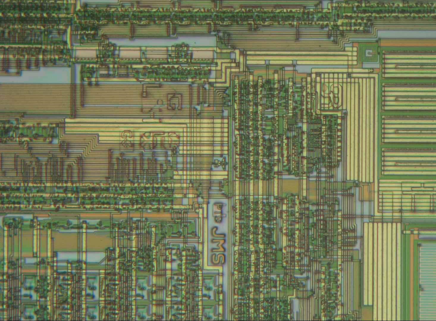
Here the designers left their initials. We see JMS in the centre, just above it (very small) “PTS”, further above there’s “GLH” with a “radioactive” symbol behind it. At the top right there’s something that looks like a monogram combining an “S” and an “R”. Below “GLH” there are a few more letters that I can’t read (any suggestions?).
Zooming in further, north of the small “PTS” we find “MC” with a bird-like logo on top of it.

All the way in the top-left corner of the die we find the fuses storing the serial number, and a list of patents claimed on the circuitry. All of these are now expired (being more than 20 years old), so any copycat manufacturer is free to implement their ideas.
This individual chip has serial number 00000CF520F2. This number, together with the family code (28) and a CRC code (B1) are stored in the 64 laser fuses in this corner, so the complete code should read B100000CF520F228. If we read the fuses byte by byte, starting at the top left, we get:
00010000 01011111 00010100 10001111
00000000 11011000 01100000 00000000
The first line has the right number of ones and zeroes to match “F520F228”, and likewise the second line could match “B100000C”. However, I can’t find a reasonable reordering that exactly matches these numbers. It’s possible that the bits have been shuffled a little in order to simplify the wiring to the fuses.
Here we see a couple of resistors (long vertical green lines) and capacitors (orange rectangles) used for the timing circuits. They are also trimmed by laser fuses. We also see several capacitors used for the “parasite power” function on the left edge and on the lower edge of this picture.
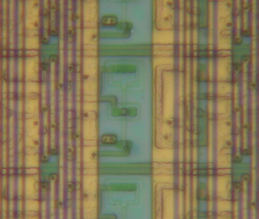
Right in the middle of the chip we find 24 copies of this structure, arranged in three groups of eight. These are the three bytes of EEPROM that can be used to store the configuration of the 18B20. That way, you can ensure that the chip always powers up in the same mode: you can select the resolution and two temperature limits that can be used to generate a special warning signal when the measured temperature exceeds a specified limit.
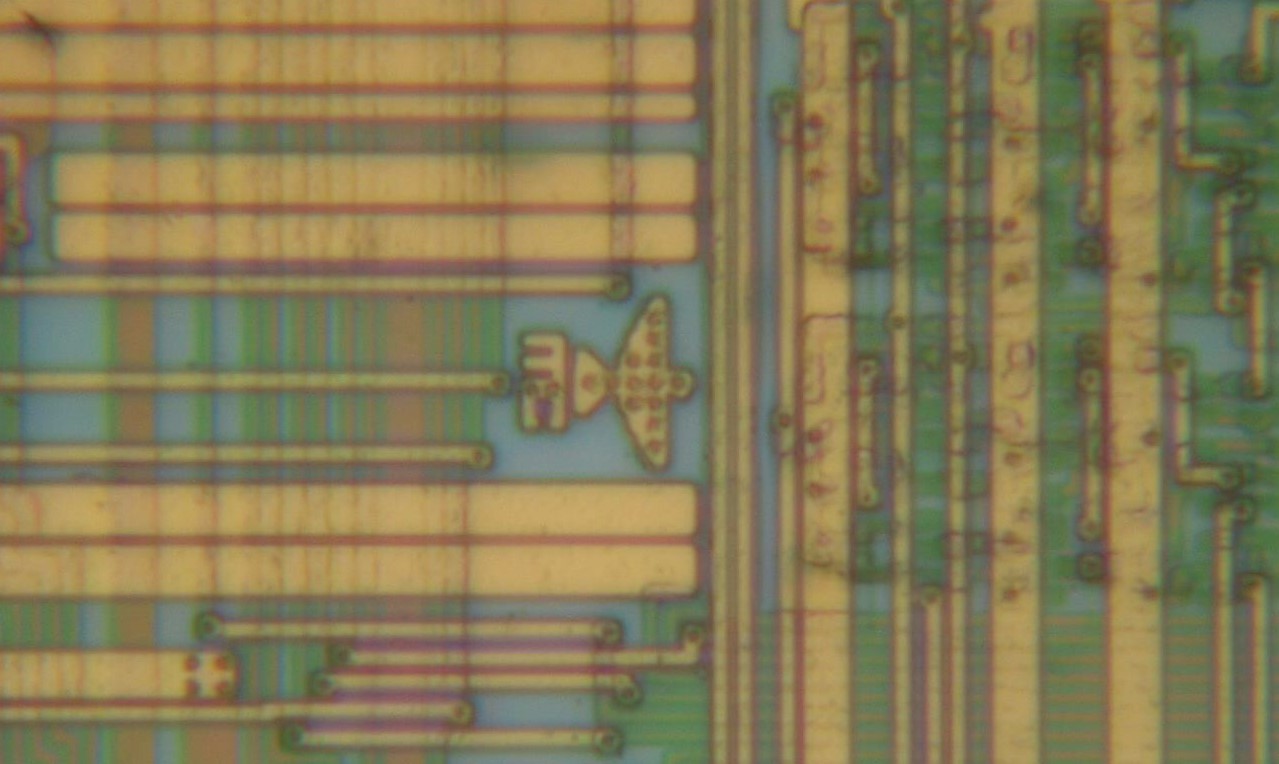
The way these memory cells work is based on a floating gate transistor: a MOSFET whose gate is not connected to any other circuits (hence “floating”), and which can therefore keep an electric charge even when no power is applied. In this picture, the floating gate is the thin vertical line right in the middle. I’m not entirely sure how the circuit works exactly, but the structures at either end of the line, as well as what looks like a transistor across the middle, provide the required read, write and erase capabilities.
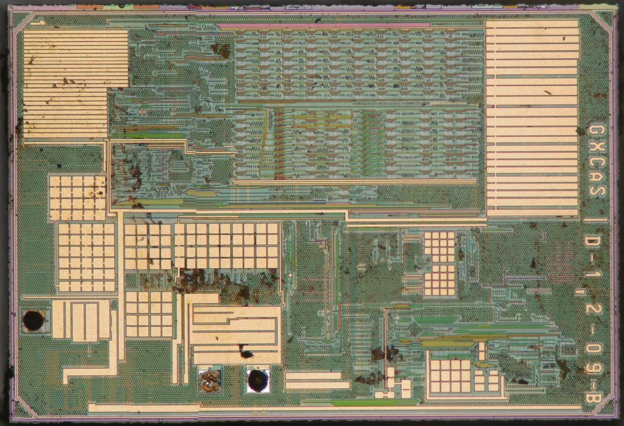
Inside the fake DS18B20 we find a completely different chip. Luckily, the manufacturer was kind enough to leave their name on the die (come to think of it, Maxim/Dallas didn’t even bother on theirs). This chip is made by GXCAS, a Chinese manufacturer that specializes in temperature sensors. They make the GX18B20, which is a pin-compatible alternative for the DS18B20, but of course sold under the GXCAS brand. Someone then re-labelled these with “DALLAS” and sold them as Maxim parts.
The part is further identified as “D-1 2-09-B”. At the top-left corner there’s also a number “1”. The output transistors are clearly visible above the two bond pads at the bottom.
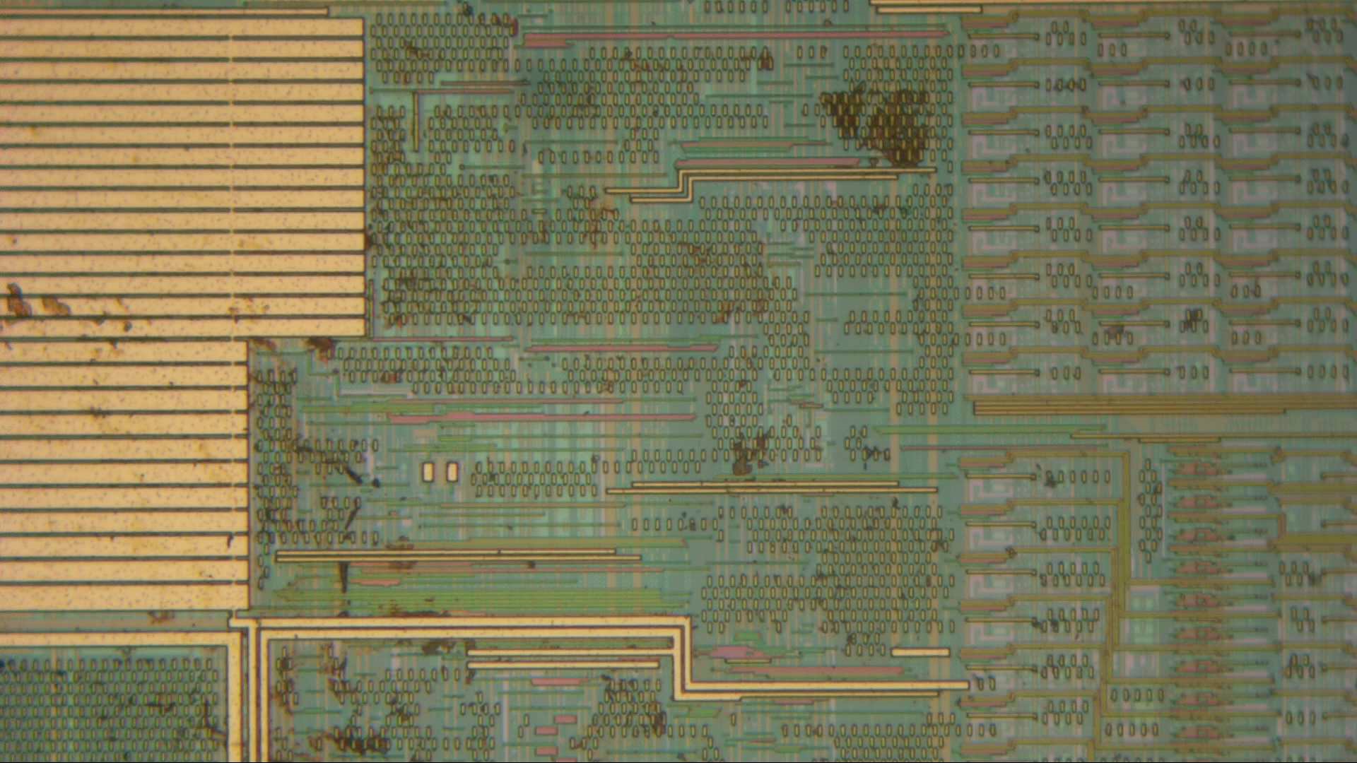
The GX18B20 was made in a much more modern IC process than the DS18B20. The top metal layer has lots of dummy shapes (tiny squares) covering most of the area. This makes it nearly impossible to see the circuits below. What is clear however, is that this chip doesn’t contain any laser fuses. Its serial number (as well as any trimming parameters) must be stored inside its EEPROM.
In fact, this may be one of the reasons why a manufacturer like GXCAS can supply this chip at such a low cost. Maxim (or Dallas at the time) had a clear reason for using both EEPROM and laser fuses: in the IC process they used, EEPROM cells are very large and only a handful can fit on such a small die. Laser fuses were much more space-efficient, although at increased cost for testing and assembly: after manufacturing, the wafer goes through a test system that probes each chip, measures its performance, and calculates the required trimming parameters. The wafer then goes through a laser machine, which scans a laser beam at each fuse that needs to be blown, thereby burning the trimming parameters as well as the serial number into each die. This is quite a slow process, and of course it requires a separate machine.
In a more modern process, EEPROM cells are tiny and it is trivial to fit dozens of them on a small die like this. Now the trimming process is much easier: the test system probes each chip, measures the performance, calculates the required trimming parameters, and directly programs these (as well as the serial number) into the EEPROM. No need for a separate machine, and no need for special process steps to enable the laser fuses.
Great job! Very informative! It would be very interesting to look inside DS3231
Thanks! The DS3231 looks interesting, I’ll put it on my list 🙂
I don’t know whether you are already aware of the fantastic research that Chris Petrich has done regarding fake DS18B20 sensors. You can see his work at https://github.com/cpetrich/counterfeit_DS18B20
This is very important find. The original DS18B20 goes up to 125 °C, but GX18B20 is going only up to 70 °C. That’s a big difference.
So you buy a fake DS18B20 and use it for temperatures around 90-100 °C and you can have a big problem.
Bought a couple of ds18b20 some years ago from China. Never got them to work (they just heat up a lot!). After some years, researching by the markings on the component body, I discovered a forum (in Germany, thanks Google Translate!), where I discovered that they are in fact NPN transistors (or maybe PNP, can’t remember right now). Love the site btw. Remembers me the Silicon Zoo.
Thanks Fabiano! The ones you mentioned are really the worst fake components, where they didn’t even bother to supply you with a similar part but just gave you any old thing that happens to be in the same package. I’m actually surprised this doesn’t happen more often; after all, how are you going to complain to the manufacturer if you’ve got no idea who they are?