The good old 741 op amp is way more versatile than I first thought. After dissecting two sets of varying designs (here and here) I managed to get my hands on even more different varieties, from all over the world, from the 1970s to the 21st century.

First up, a 741CE sold by Teledyne. It’s packaged in a “metal can” type package, which is exactly what it sounds like. These were popular in the 1960s and 1970s to package integrated circuits, as a logical evolution from transistors: manufacturers simply increased the number of pins from three to whatever number was needed to wire up the IC. However, this became impractical for more than about ten pins, and plastic or ceramic DIP packages became the norm from the late ’70s. These were also much cheaper to produce and more suitable to automated assembly. It’s clear to see that a previous owner manually bent the leads of this chip to fit it into a DIP-8 footprint on a PCB.
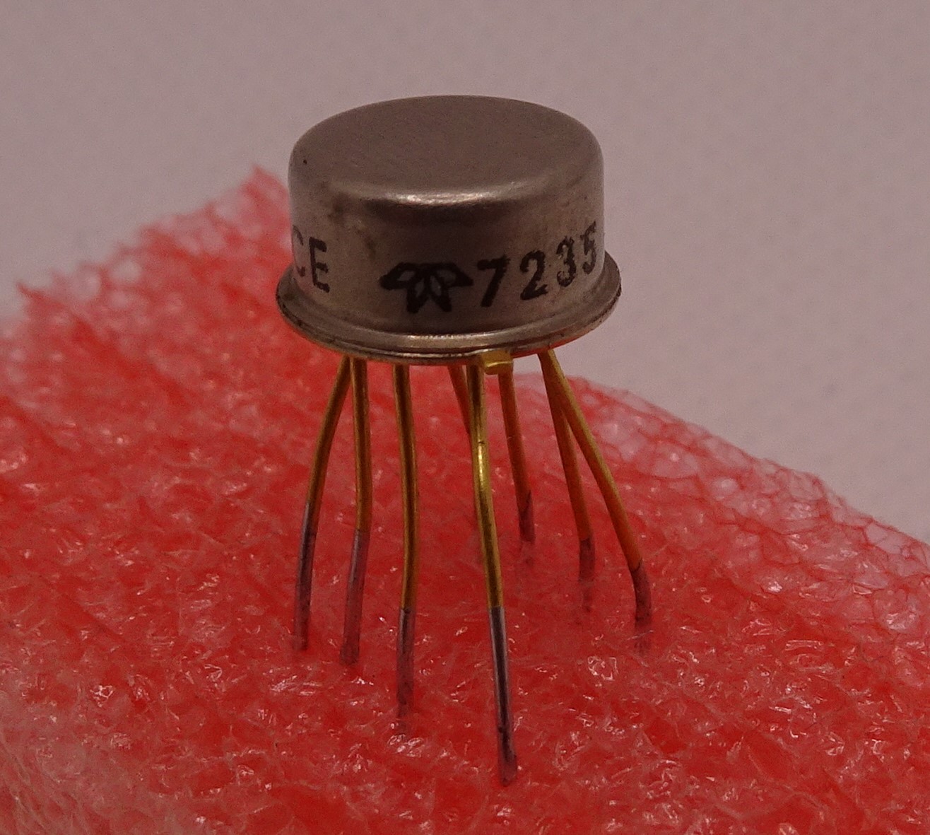
This particular chip has a 1972 date code. The Teledyne logo is the same as it is today, nearly half a century later, but the Teledyne corporation has changed significantly. Founded in 1960, it started out producing electronic components but quickly grew into a sprawling conglomerate with interests ranging from jet engines to shower heads. Today it still has dozens of business units, mostly in high-tech sectors including semiconductors, although now focussing on specialized applications such as RF devices and image sensors. I wasn’t able to find a Teledyne datasheet for the 741; if you have any information please let me know!
Inside we see a neat and clear layout. It contains a copyright mark but no date, a stylized Teledyne logo and a “741” identifier. There is a long, meandering resistor to set the bias current, taking up quite a lot of space. The NPN input transistors are the only ones on the die with round emitters; all other transistors are square. I would assume this was done for matching reasons, since round transistors tend to make better matching pairs. Why this wasn’t done with other transistors is unclear, because it doesn’t look like the round devices take up more space than the square ones. At the top left corner there is also a test structure with three probe pads that could be used to test production parameters.
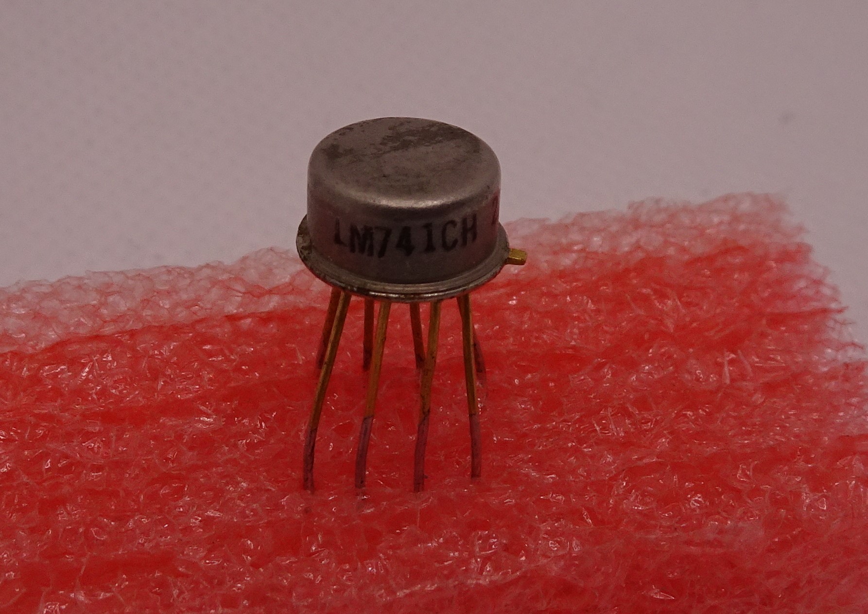
Next up is an LM741CH by National Semiconductor, also in a metal can package. We’ve looked at National’s LM741 before, but this is a much older example and likely to be of an earlier design.
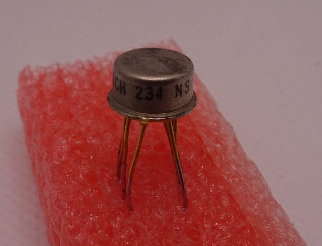
The letters “NS” identify the manufacturer, while “234” is a date code most likely pointing to 1972, week 34. Again, the legs have been awkwardly bent to fit in a DIP footprint.
The die is in fact very different from the ones we saw before. For some reason, this die says “RM741” at the lower edge and “741Y” on the right side. There are test structures in the lower right corner and “=”-shaped alignment markers in the four corners. Also odd to see is the empty diffusion in the top-right corner.
All transistors are square and there is quite a lot of empty space around them, unlike National’s most recent layout.
Continuing our journey through the 1970s, here is a Motorola LM741CN from 1978. Unlike the 1987 chip we looked at earlier, this one actually uses National’s “LM” designator rather than Motorola’s “MC”. This puzzles me a bit: I cannot find any information on Motorola calling their chip anything other than “MC1741”.
Inside we see several odd things. The spiky metal features make the round input PNPs look kind of funky. But the weirdest bit is the compensation capacitor: it takes up all of the dark blue area, but it looks like most of that is wasted because the top plate is only the green bit covered with metal. Maybe Motorola optimized their IC process to get a larger capacitance per area, but couldn’t be bothered to do a complete re-layout of this design?
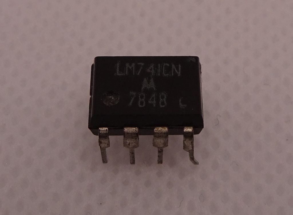
I wrote earlier that TI and ST were the only manufacturers still producing the 741 today. But I was wrong: as it turns out, a Chinese company named HGsemi also produces their version of the LM741. Confusingly, there are two entirely different companies doing business under the name “HGsemi”: there’s Huagao Semiconductor, which makes RF transistors, and Huaguan Semiconductor, which makes a wide variety of analog chips including this opamp.
Unfortunately, Huaguan didn’t bother to make a proper datasheet of their own and just copied a few pages from National’s, even leaving intact the instruction to contact National Semiconductor’s sales office in case of questions!
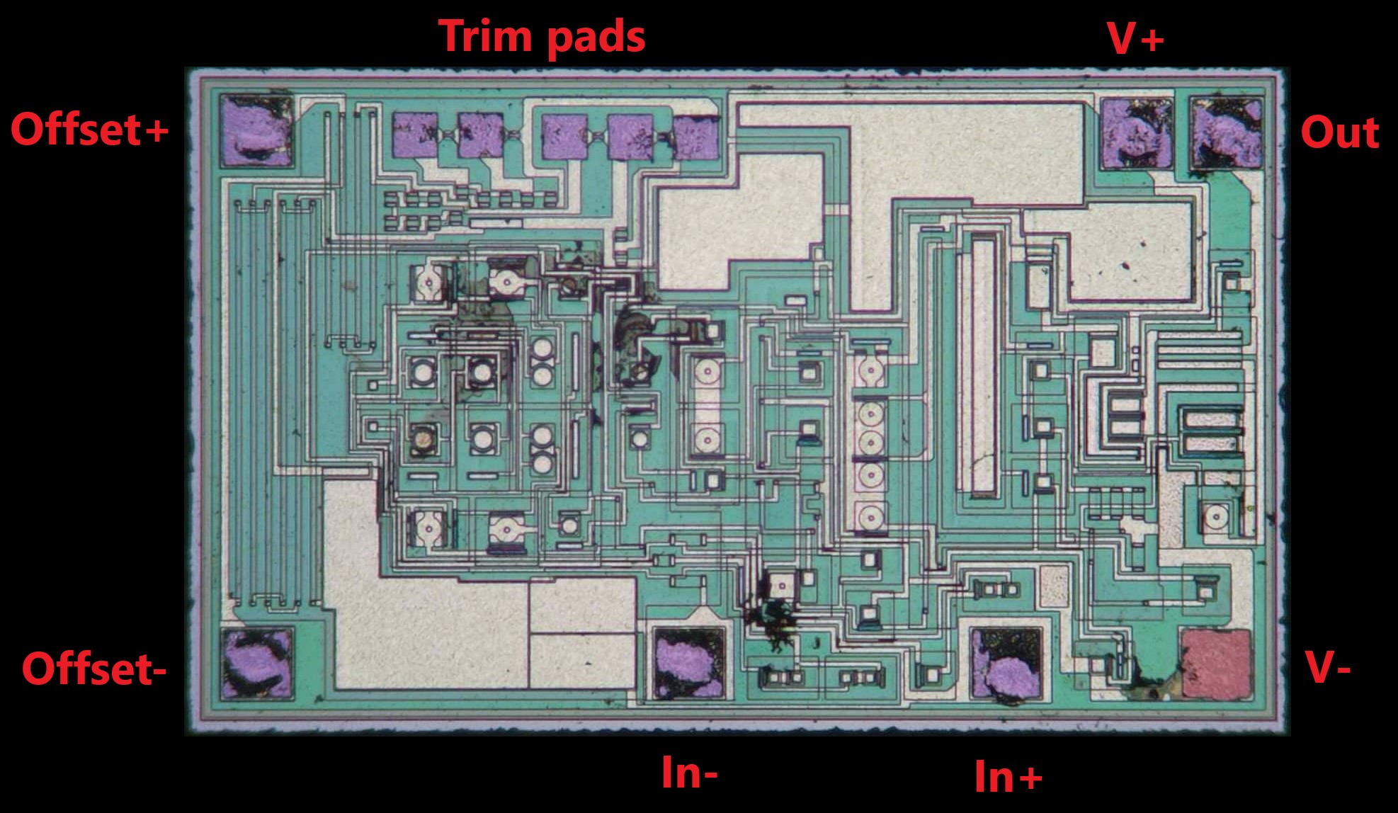
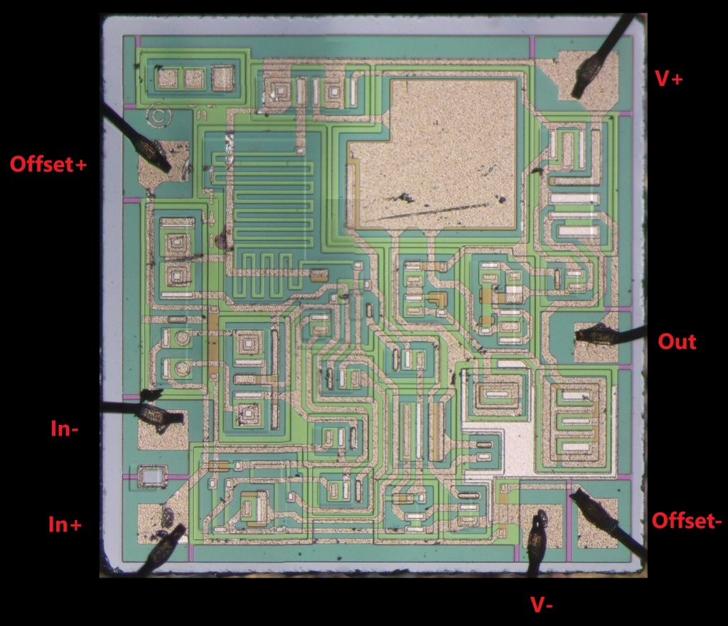
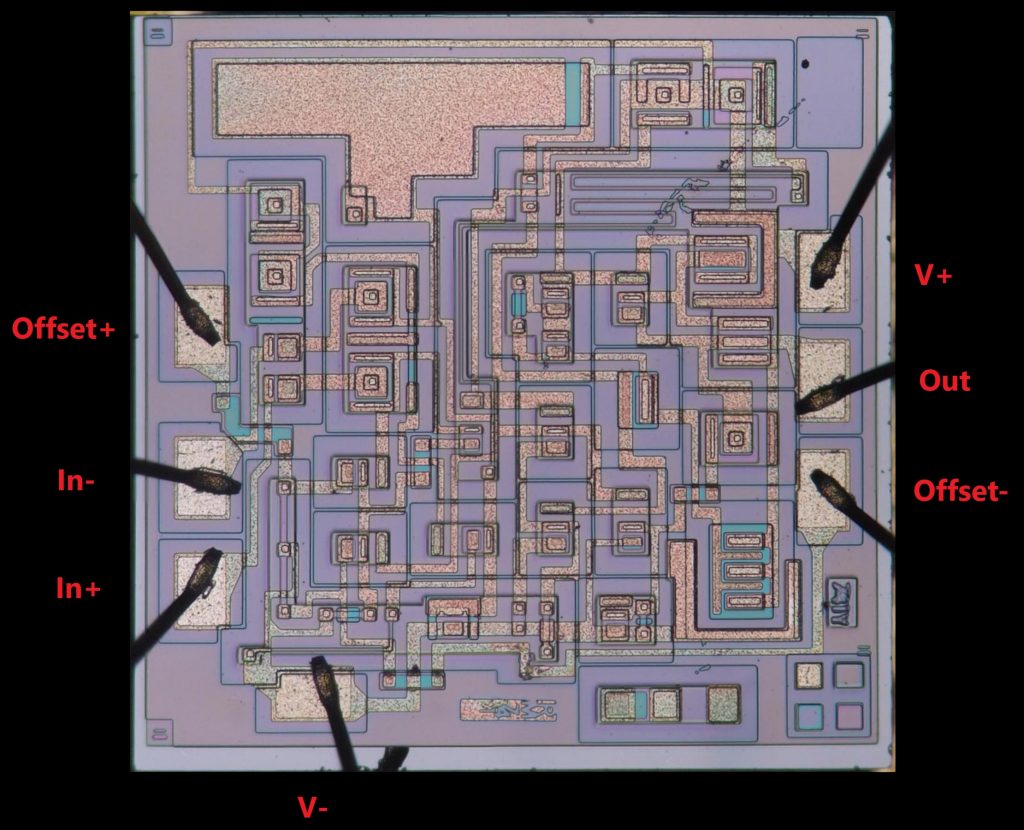
Inside it’s completely different from all the 741s we’ve seen so far. If I measure the chip on the outside, I find that the offset pins have a resistance of about 15 kOhms to V+, not 1 kOhm to V- as you would expect. In fact, this is most likely not a 741 at all, but an OP-07, which HGsemi also supplies. Although there are no die markings to indicate the manufacturer or even the chip type, the overall layout matches the internal circuit of an OP-07. At the top we see the trim pads, with fuses between them that are blown to trim the input offset. In the middle are several round PNP transistors forming matched pairs. The two pads on the left are the offset trim pins.
Designed by George Erdi at Precision Monolithics in 1975, the OP-07 was a far more advanced op amp design, although still nearly pin-compatible with the old 741. But the two chips are still different enough that they’re not direct substitutes: the OP-07 has 600 kHz of bandwidth compared to the 741’s 1 MHz, has a much lower offset voltage (0.25 mV vs. 6 mV), but uses more power (2.4 mA instead of 1.7 mA). Also, if you want to use the offset null capability, you should connect a potmeter between the offset null pins with the wiper connected to V+ (for the OP-07) or to V- (for a real 741).
The fact that HGsemi put a “741” label on an entirely different chip is at least poor practice and borders on fraud. But things can get even weirder, as we shall see below.
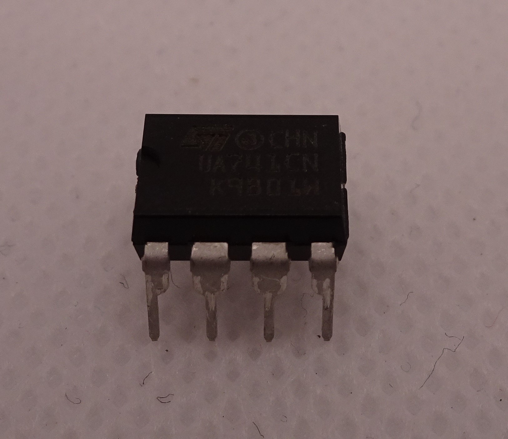
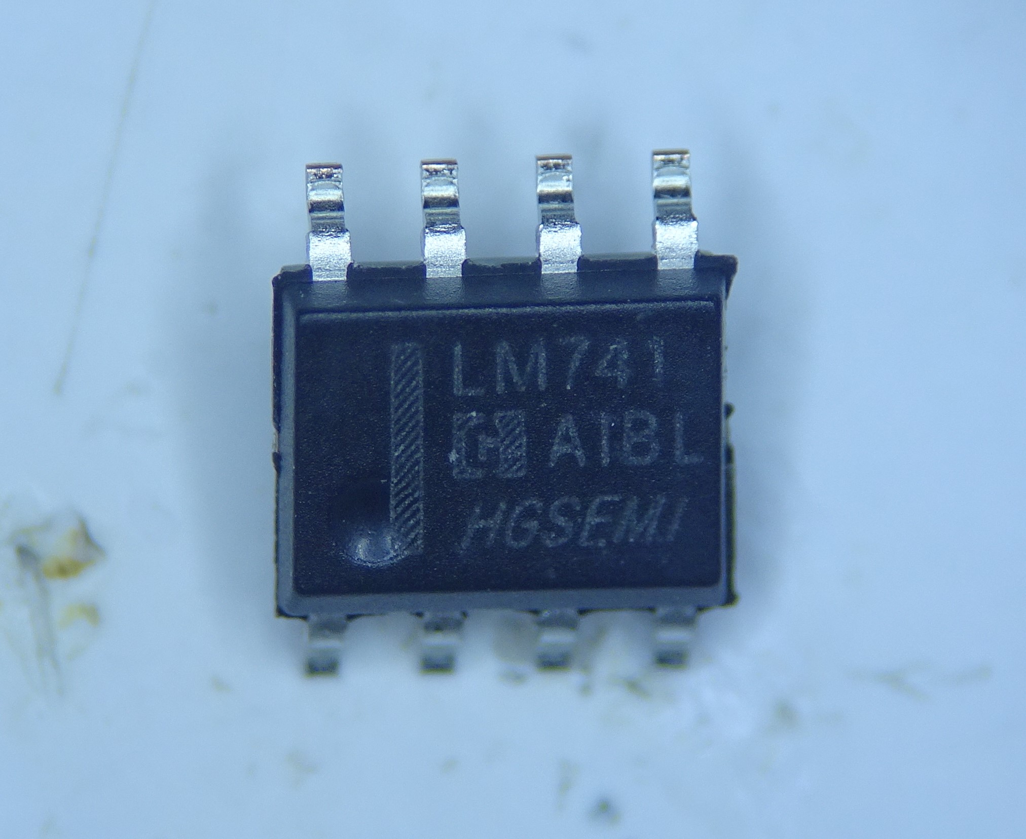
I bought a bunch of these “ST UA741CN” chips online for just €0.052 each. The markings are laser etched, but the package is of poor quality with lots of bits and pieces of plastic sticking out. Measuring the offset pins gives an open circuit this time.
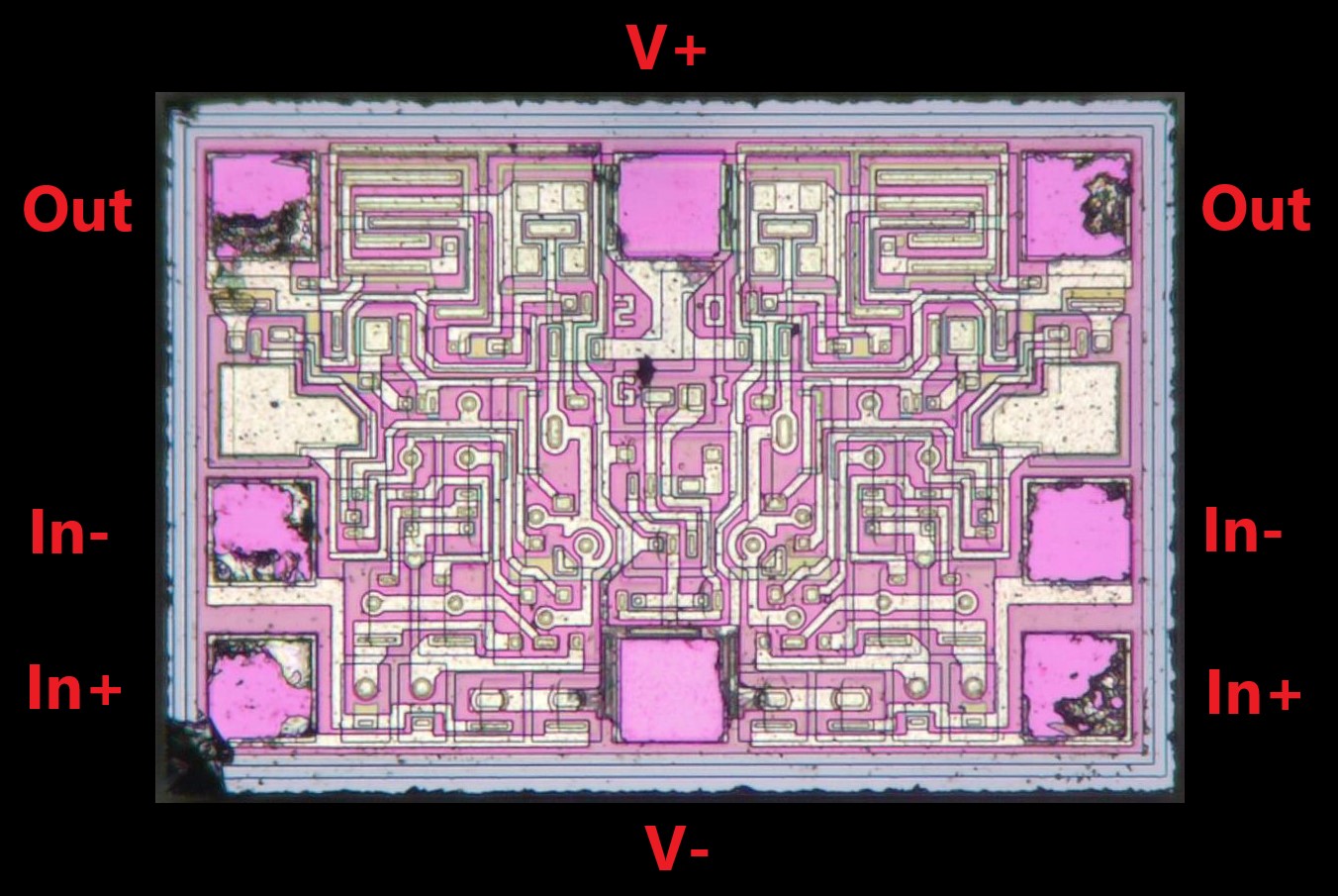
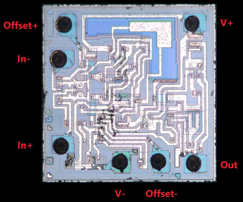
Inside it’s clear why: there are no offset adjust pins! What we’re looking at is a dual opamp: the left and right halves of the chip are mirror images, with the supply pins in the middle. It would make sense if this was a dual 741, which exists and is called the MC1458, but the basic circuitry doesn’t look like it. My guess would be that this is an LM358 or something similar, as you can see below.
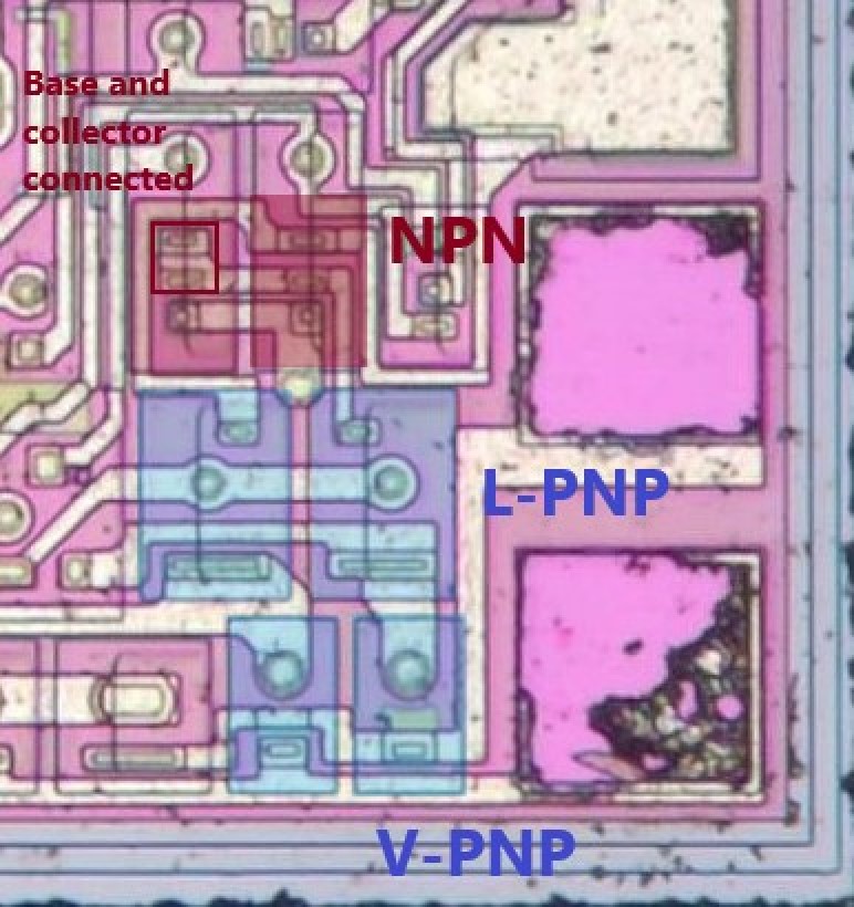
Here I’ve highlighted the input stage: the inputs go into a pair of vertical PNPs, which connect to a pair of lateral PNPs, followed by a pair of NPNs, one of which is diode-connected. The LM358, which is a very cheap dual opamp, has an input circuit like this, as do several derivatives. An original one from TI costs only about 4 or 5 cents, so I can imagine that you could turn a profit by re-labelling one from a cheaper manufacturer and selling it for 5 cents. You’d have to sell thousands of these things to make it worth any investment, but apparently it works: fake op amps like this are widely available online, suggesting that there is money to be made with them.
Hi, thanks for this article, I check ST UA741CN yep they are open,
but for TL071, TL081, and LF351 from ST, I measure about 3K,
just curios maybe this is re-label as UA741.
Hi i.wan, all these op amps have a similar offset adjust circuit to the 741. If you measure between either offset pin (1 or 5) and ground (4) you should measure about 1 kOhm (give or take 30{684d88caeaea11df97b4707db4900e0b3a8d2f739f69707463db5f51e5389d4d}). If you measure between pins 1 and 5 you should measure double this number. So 3 kOhm seems about right, but that should be the same on the TL071, TL081, LF351 and the 741, so you can’t tell these chips apart using just this measurement.
I double-checked everything, and it’s in accordance with what you said.
I have
LM741 NS 2K, HA17741 2K, AN1741 2K
UA741 TI 3K, Philips UA741TC 3K
so my assumption for LM is around 2K and UA 3K even though different manufacturers
for LF351 NS the value is around 22K – 26K
while for the LF351 ST the value is 3K which makes me confused
I also measured TL071 TI and TL081 TI 2K, for LF351 TI I don’t have it
while for ST TL071 and TL081 the value is 3K
maybe because of this each manufacturer also makes,
so I can’t predict it.
At least I can tell that my UA741 ST is not compatible
Thank You very much, Robo, for your explanation.
i.wan, one IC that I (and many other designers & engineers) would like to see opened up and reverse engineered is the LM386, including chips from other manufacturers too.
i.wan, another now discontinued IC that I (and many other designers & engineers) would like to see opened up and reversed engineered is National semiconductors LM383, they tried to reverse engineer SGS TDA2002, that’s how they came up with the LM383. The website that I found this information on is: http://www.idea2ic.com And maybe the TDA2002 to see how close they (NS) got.
Another discontinued IC that I would like to see opened up and reverse engineered is the LM386, use National Semiconductor and Texas Instruments IC’s as a reference though.