After dissecting a whole batch of 555 timer ICs I thought it would be an interesting project to make a working copy of the 555’s internal circuit out of discrete components, in the same physical space as the original IC. I’ve done this before with the 741 opamp, and the steps are similar. First, I drew the schematic in KiCAD:
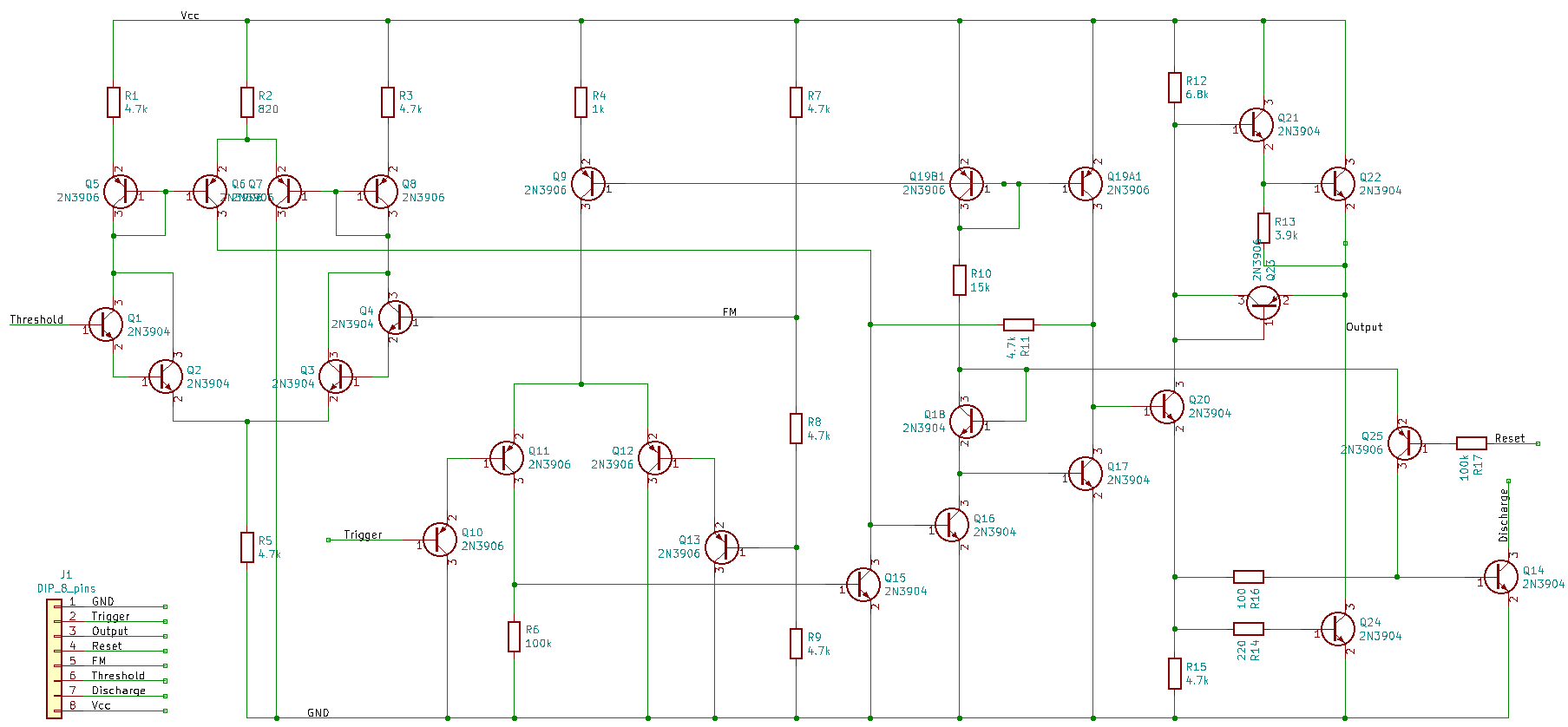
I used the original circuit as designed by Hans Camenzind, as a tribute to his design but also because it uses the smallest number of transistors among all different designs I found while dissecting the various 555 ICs. Discrete transistors are larger than discrete resistors, so the original design saves space compared to newer versions that include several more transistors. Note that it’s the opposite situation when you’re designing an actual IC: integrated resistors are usually the largest parts in your layout.
The total bill of materials for the TT555 comes to 26 transistors and 16 resistors. I’ve added a 100 kOhm base resistor to Q25 to protect it from damage, because most transistors cannot withstand more than about 1 V across their base-emitter junction. The lateral PNPs used in integrated circuits are actually very poor transistors with low gain and a high base resistance, which can however withstand rather high voltages across their base-emitter junction without breaking down.
I decided to use 2N3904 and 2N3906 transistors for the design because they can draw the 200 mA that the 555 can deliver on its output pin. These transistors are very commonly used in all kinds of electronic circuits, but usually in the traditional TO-92 package (4.6 x 4.6 x 3.8 mm3). For the TT555 I chose the DFN1006 versions, sold by Diodes Inc as the MMBT3904LP and the MMBT3906LP, which measure only 1 x 0.6 x 0.5 mm3. Below you can see how the transistors (on the black tape) and 01005 size resistors (on the white tape) compare to an old 555 chip.
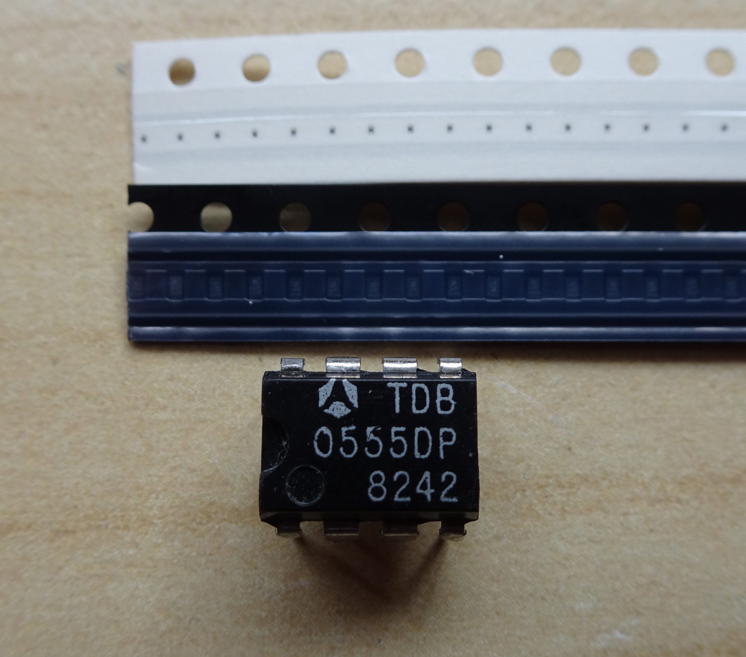
All resistors are 01005 size (0.4 x 0.2 mm2) except R11 and R12 (0402 and 0201 respectively), because they can dissipate more than the 0.03 W rating of the 01005 package. Also, to make routing a bit easier I chose a four-layer PCB this time (the TT741 was dual-layer). A few evenings of layout work and about two weeks of processing at the PCB factory finally resulted in a nice batch of 10 x 10 mm2 PCBs:
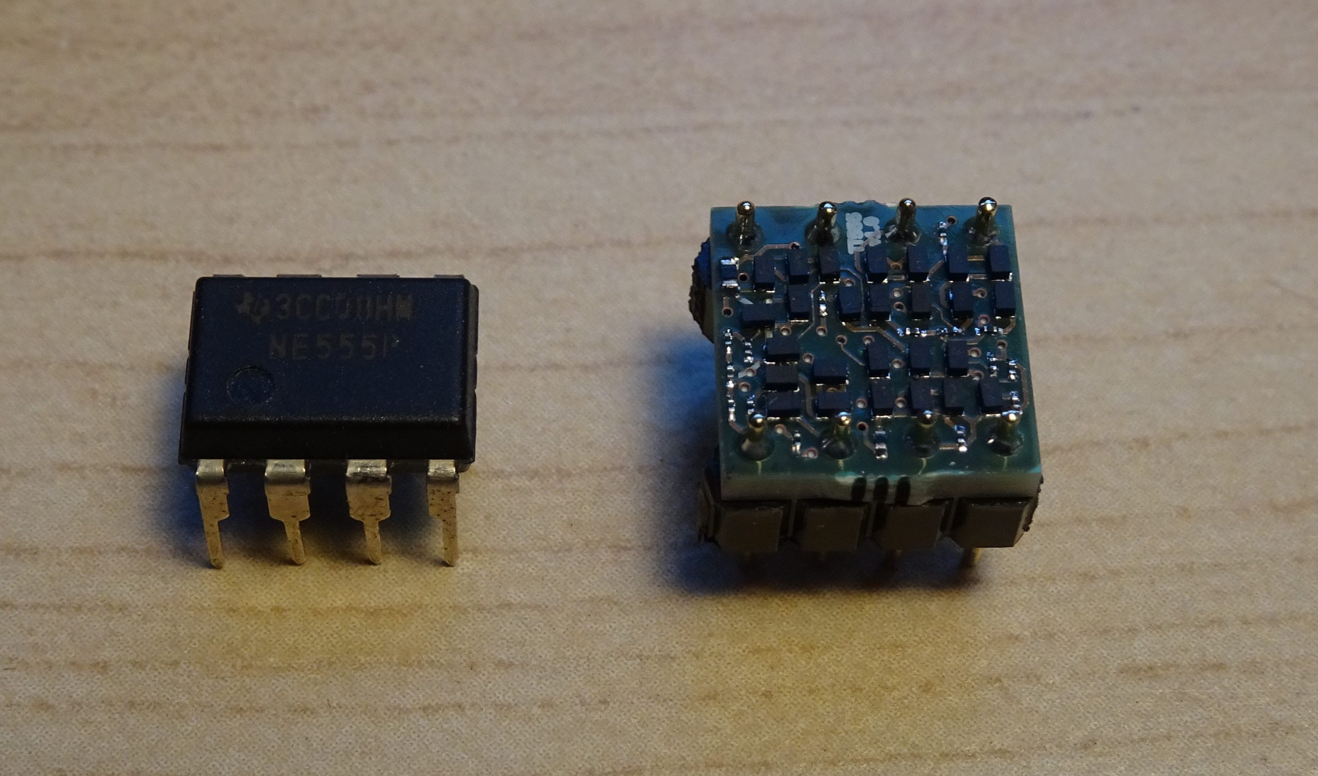
Soldering went surprisingly easily. Building on my experience assembling the TT741 I had developed a feel for the proper amounts of solder, flux and heat needed to correctly solder these tiny DFN1006 packages. Below is the result.
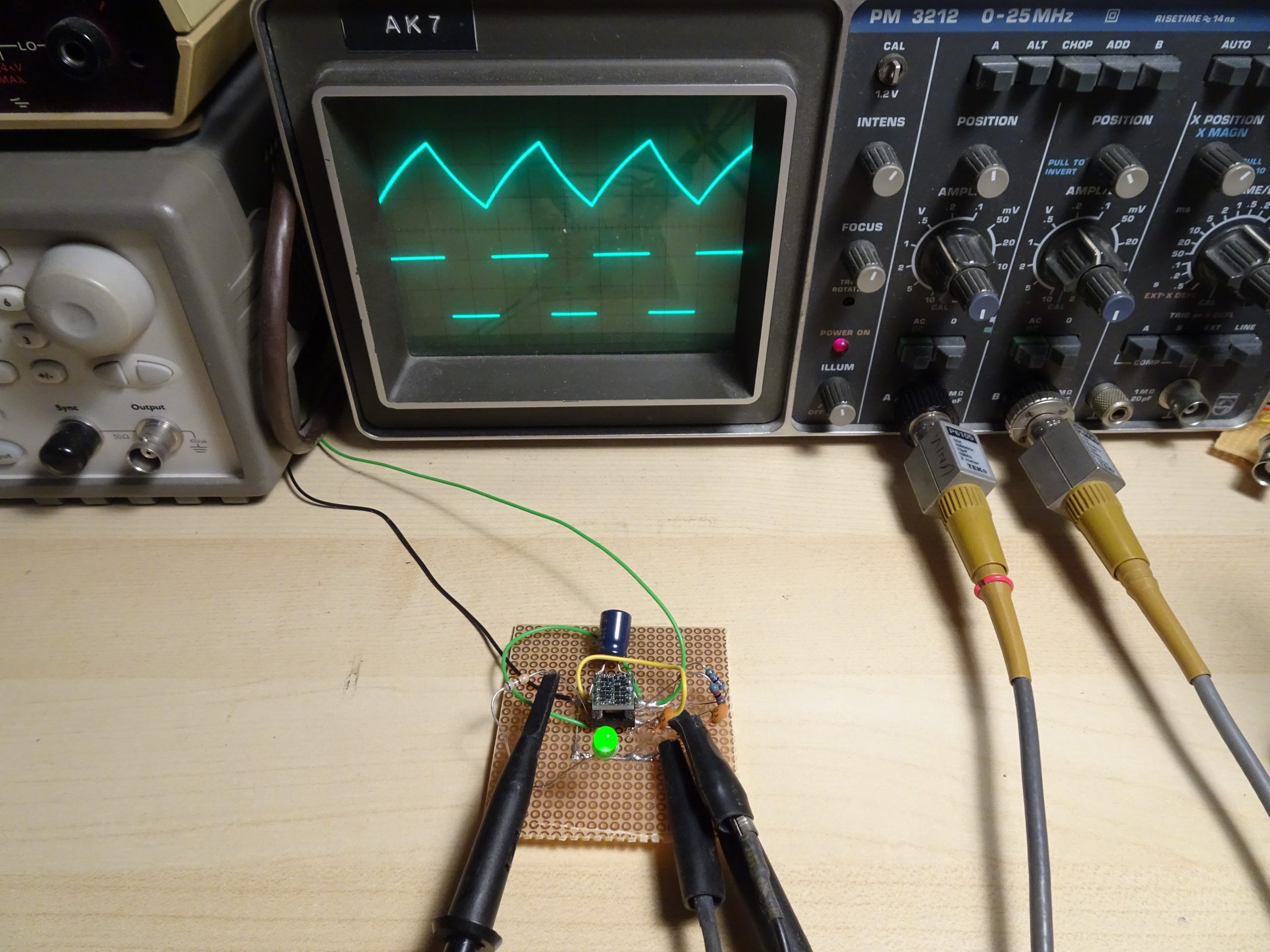
And of course, the proof of the pudding is in oscilloscope traces, so I made a little test board to run the TT555 in astable mode, producing a nice clean 670 kHz frequency:
“The soldering went easy, however my eyes and fingers are now damaged beyond repair”
Can you share the files? I’d love to try this myself.
?! I started reading and thought, “well, this guy projected a discrete-555 with tiny SMD components, and since he have acess to industrial pick-and-place and wave soldering machinery, the device was built this way.”
The greater hacking hability in this case is soldering this board manually!