CMOS 555 Timers

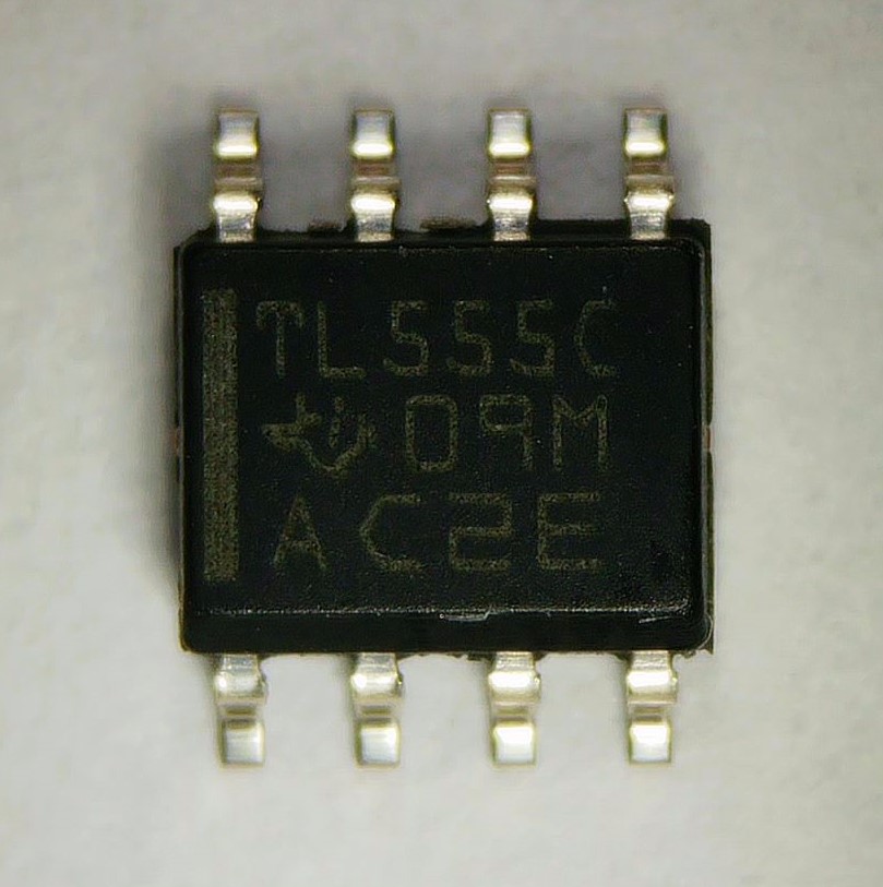
Although the 555 timer is one of the most iconic chips ever made, and the original version is still sold in huge numbers, it actually makes little sense nowadays to use the classic chip anymore. That’s because an improved version has been around for a long time: the CMOS 555 timer. Most manufacturers that produced the original bipolar 555 timer also make a CMOS version, with typically the letter “C” somewhere in the full product name. Today we’ll have a look at a couple of these CMOS timers and see how they differ from the bipolar model.
Continue reading

TT555 Soldering Kit now available on Tindie!

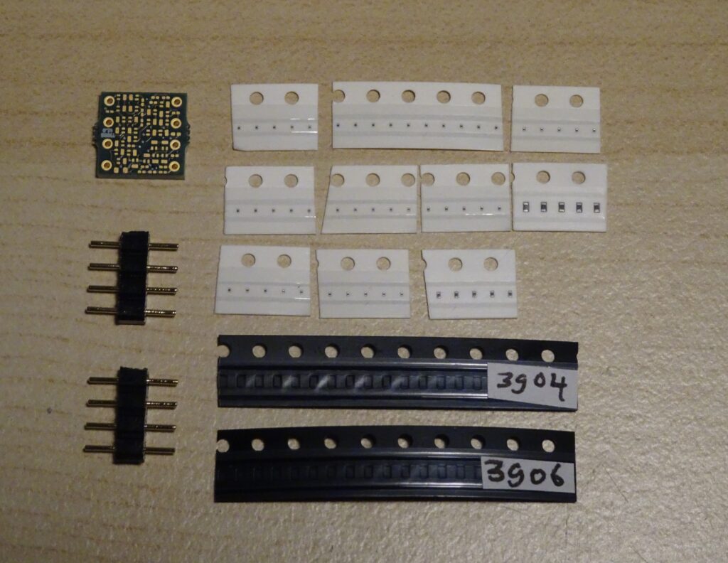
Probably the most-viewed post on this blog so far has been my project to construct a discrete-transistor replica of the 555 timer IC. I’m pleased to report that, due to popular demand, the TT555 is now available in kit form!

This is your chance to prove that you’re a real SMD soldering expert: to assemble it, you need to place 43 components onto a 10×10 mm2 PCB, pick and place 01005 size resistors (0.4×0.2 mm2), and solder DFN-1006-3 packages (1.0×0.6 mm2). A microscope, sharp tweezers and a fine-tipped soldering iron are essential tools to complete this project.

Please click here to find the TT555 on Tindie!

Continue reading

The 555 timer – part 2

Today we’ll look at a couple more versions of the 555 timer. Like the 741, this chip has been produced by many different manufacturers in the nearly five decades since its introduction by Signetics in 1972.

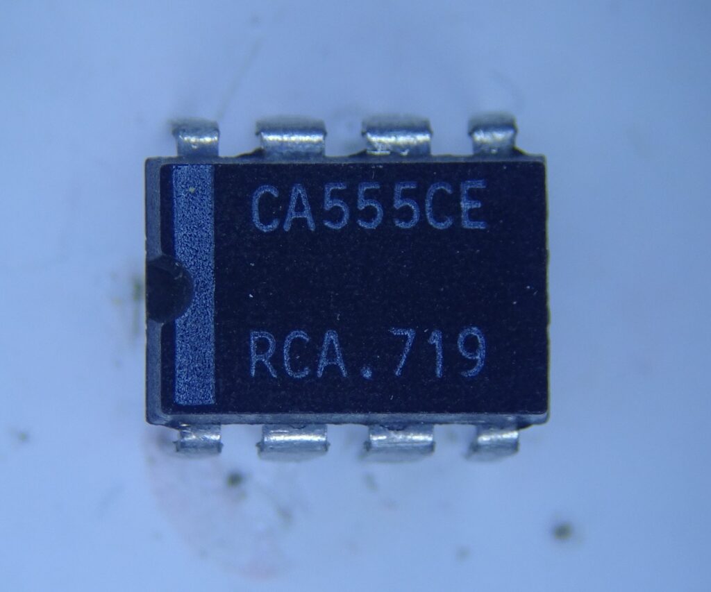
First up is RCA’s CA555. Packaged in an 8-pin DIP (which is what the “E” in “CA555CE” stands for), this is a “C” spec which can work at up to 16 V, unlike the CA555E that is spec’ed up to 18 V. I’m not sure what the actual difference between these two would be; I guess the chips were sorted after production, with parts that marginally failed some spec at 18 V being demoted to “C” versions.

Continue reading

The TT555: a discrete 555 timer plug-in replacement

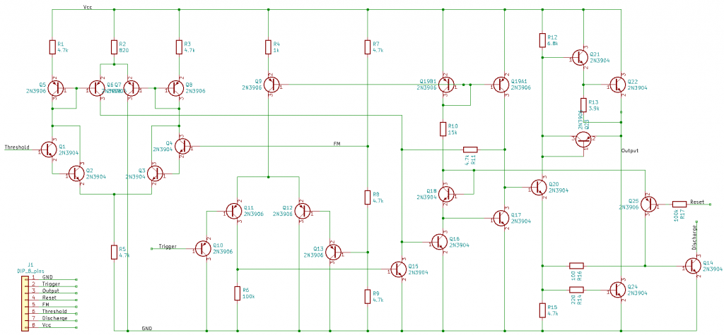
After dissecting a whole batch of 555 timer ICs I thought it would be an interesting project to make a working copy of the 555’s internal circuit out of discrete components, in the same physical space as the original IC. I’ve done this before with the 741 opamp, and the steps are similar. First, I drew the schematic in KiCAD:

I used the original circuit as designed by Hans Camenzind, as a tribute to his design but also because it uses the smallest number of transistors among all different designs I found while dissecting the various 555 ICs. Discrete transistors are larger than discrete resistors, so the original design saves space compared to newer versions that include several more transistors. Note that it’s the opposite situation when you’re designing an actual IC: integrated resistors are usually the largest parts in your layout.

Continue reading

The 555 timer

If there’s a classic analog chip even more iconic than the 741 op amp, it has to be the 555 timer. Released just three years after the 741, it similarly took the world by storm, selling billions of units over five decades. Quite unlike the 741, which established op amps as a common IC type, the 555 has remained largely in a class of its own. There are many ICs that can generate square or triangle waves, but I can’t think of any chip that can function as a one-shot, a flip-flop, Schmitt trigger, or one of a million different oscillator types like the 555 can.

Designed by Hans Camenzind in 1972, its story is described in detail in Camenzind’s own book Designing Analog Chips. I highly recommend reading it (available on paper or as a free download) if you’re interested in analog IC design. In Chapter 11, Camenzind shows the schematic of the original 555 timer:

Continue reading