I recently read a forum thread where someone showed how a set of LME49710s that he bought online didn’t function the way they should. Although the chips apparently contained an op amp, they were unable to amplify a 60 kHz square wave and output a triangle wave instead. This means that the op amps’ slew rate is too low: the LME49710 is specified to reach 20 V/us, but these chips only managed 0.5 V/us or so.
The thread’s author asked if anyone could help identify his chips, and I offered to examine them for him. A few days later I received the op amps in the post. They were clearly marked with the National Semiconductor logo and “49710” as a model number:
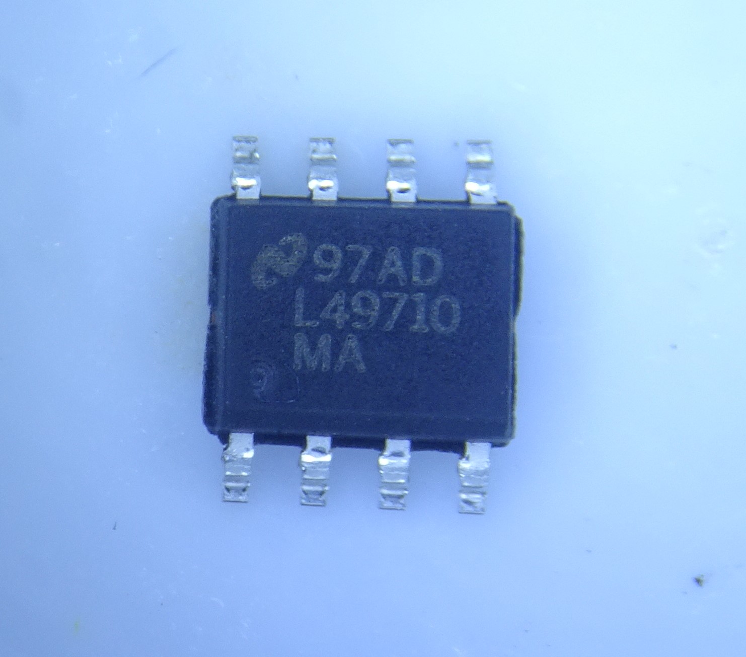
I haven’t got any real LME49710s lying around for comparison, but the chip looks all right at first sight. The markings are laser etched and the package doesn’t seem to have been painted over or sanded down. The plastic is of reasonable quality, although the mold flash is slightly out of spec: National’s datasheet specifies 0.15 mm as the limit, while the flash on the left side of the package is about 0.2 mm.
The LME49710 is an ultra-low distortion audio op amp. It was discontinued by its manufacturer several years ago, so any chips you can buy today are either old stock or counterfeit. The dual version (LME49720) is still available however, so if you need new chips to replace those in an existing design you might have to make a slight modification to your board.
To find out if the suspect LME49710s were any good, I decided to run a little slew rate test to see if I’d get any reasonable values. I set up the chip as an inverting amplifier with a gain of -1 and applied a square wave on the input with a peak-to-peak value of 20 V. The supply voltage was +/- 15 V.
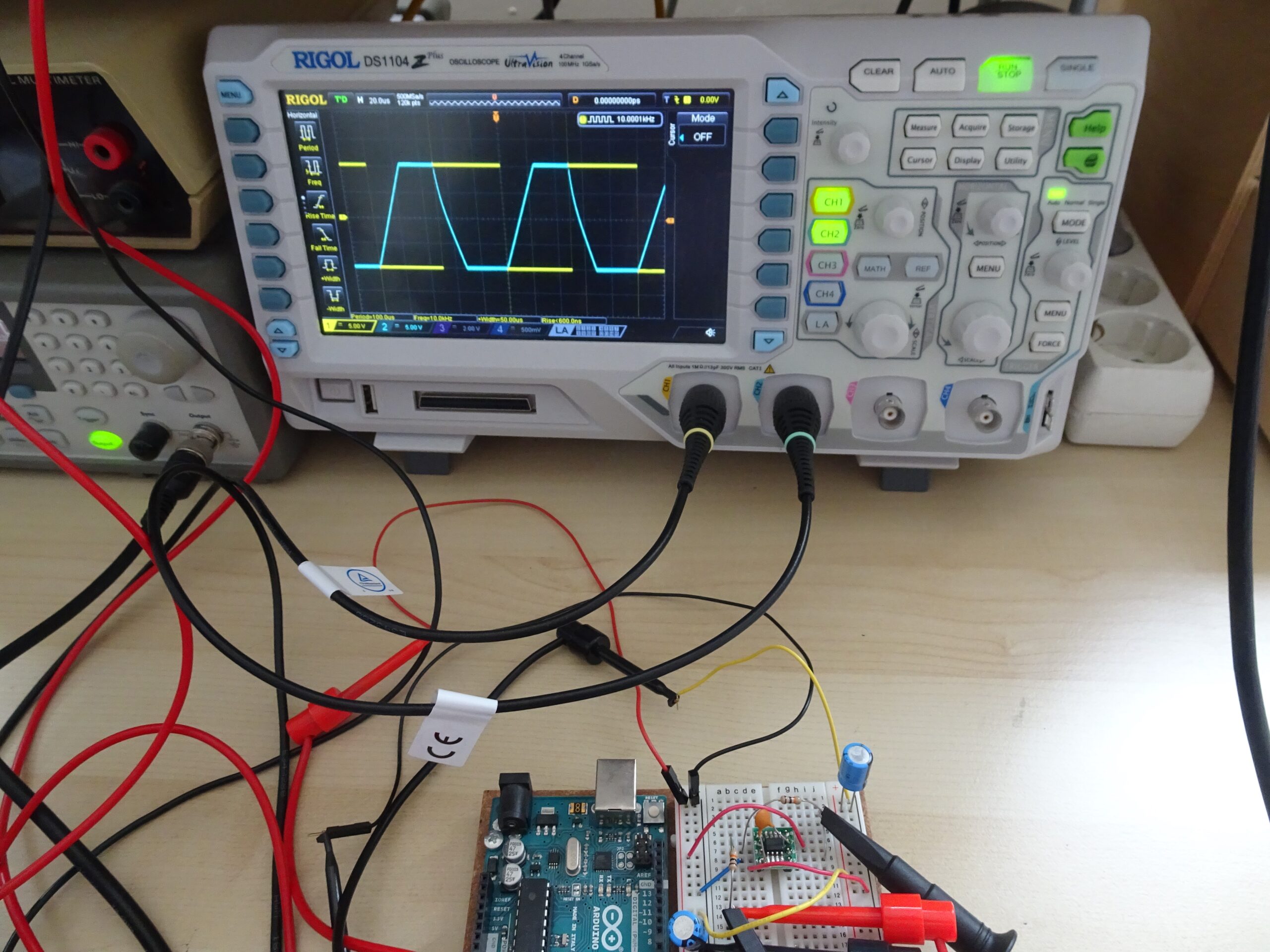
The blue curve shows the amplifier slewing. The slope is a little under 1 V/us, which is way less than the 20 V/us mentioned in the datasheet. Clearly something’s not right here. Time to open up the package!
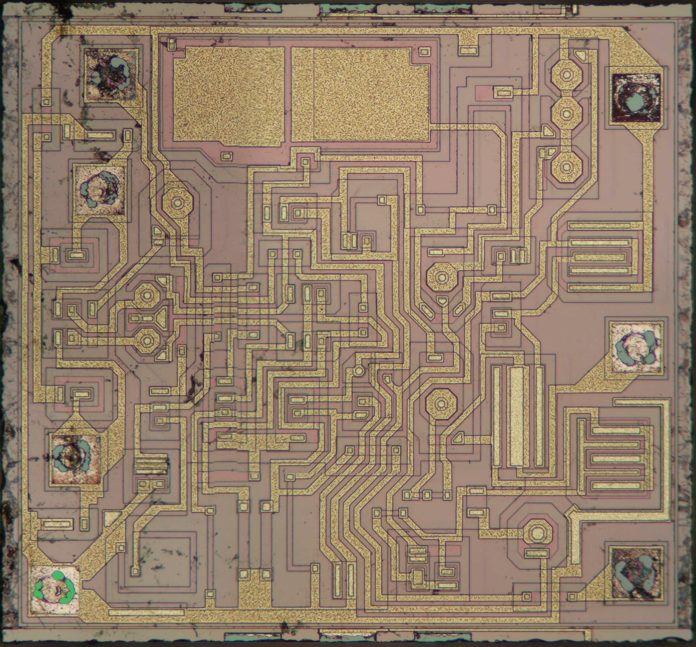
Inside, we find this nice little bipolar design. There’s a large compensation capacitor at the top, symmetrical input circuitry on the left and large output transistors on the right. There are no logos, revision numbers or product IDs anywhere on the die. However, the layout looks very similar to something we’ve seen before: the UA741 made by ST.
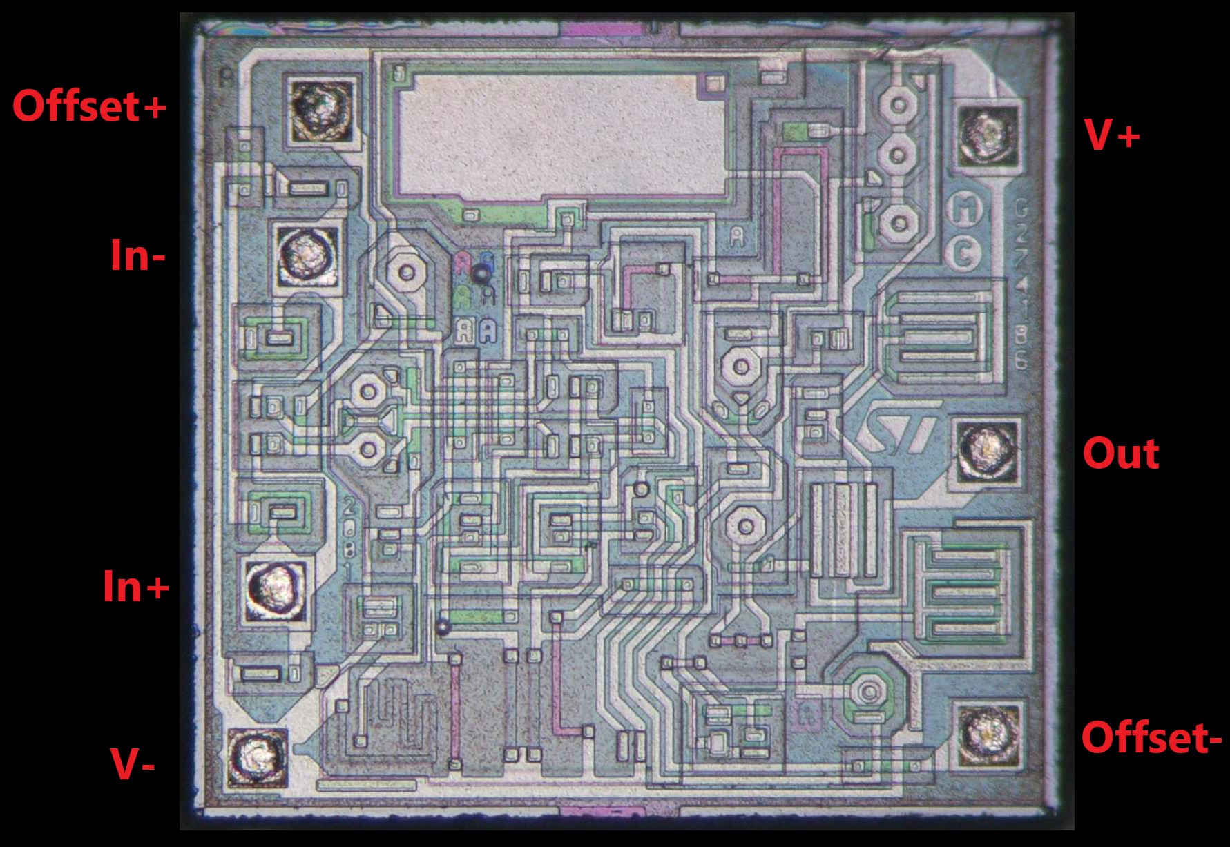
As you can see, the design is almost completely identical, although there are a few small differences. The logos and revision letters have been removed, so it’s unclear who made the fake chips. The compensation capacitor seems to have been cut almost in half, and the biasing resistor in the lower-left corner has lost a few meanders.
One notable difference between the 741 and the LME49710 is the presence of offset adjust pins: on the 741 pins 1 and 5 are used for that purpose, while on the ‘49710 those pins are unconnected. However, if I measure the resistance between pin 1 or 5 and the negative supply pin I get about 1.2 kΩ, which would be expected from a 741. The measured slew rate is also correct for the 741, for which it’s typically specified as 0.5 V/us.
There’s no doubt that the dodgy LME49710s are in fact relabelled 741s. Who made them remains unclear, but they definitely copied ST’s layout and probably modified it slightly to adapt it to the manufacturing process they had available. Although these chips might “work” to some degree in a real application, they will sound horrible if used for audio and will not reach anywhere near the performance you’d expect from a real LME49710.